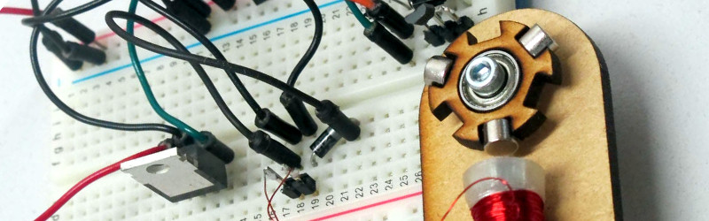
Sometimes there is no substitute for a real working model to tinker with when it comes to understanding how something works. Take a brushless motor for example. You may know how they work in principle, but what factors affect their operation and how do those factors interact? Inspired by some recent Hackaday posts on brushless motors, [Matt Venn] has built a simple breadboard motor designed for the curious to investigate these devices.
The rotor and motor bodies are laser-cut ply, and the rotor is designed to support multiple magnet configurations. There is only one solenoid, the position of which relative to the magnets on the rotor can be adjusted. The whole assembly is mounted on the edge of a breadboard, and can be rotated relative to the breadboard to vary the phase angle at which the drive circuit’s Hall-effect sensor is activated by the magnet. The drive circuit in turn can have its gain and time constants adjusted to study their effects on the motor’s running.
[Matt] has made all the design files available in his GitHub repository, and has recorded a comprehensive description of the motor’s operation in the YouTube video below the break.
[Matt Venn] has been featured on these pages quite a few times in the past. Whether it’s his home-made cargo bike, his webcam-based home energy meter, or his halftone G-code generator, he’s one to watch! Meanwhile, here’s the brushless motor we featured in 2015 that inspired him.


Nice simple design and great presentation. Reminds me of a reed switch motor I made in a salt canister…but this is a lot more elegant.
This is super cool and looks simple to build. I would love to use this in some of my classes.
What is very hard for me to understand is why people insist making air-core motors. Can we please put some form of steel there, even if it is from an ugly clamp?
how do you mean? There is a bolt through the coil – am I missing something?
Yes, you are missing the rest of the magnetic “circuit” to provide a flux path from the back of the solenoid back around to the rotor, and within the rotor itself which is plywood rather than something like iron laminations. Providing no path better than air/plywood for these large distances substantially weakens the motor – a real motor keeps the gaps as small as possible.
This is a demonstration motor designed to show the principles behind BLDC motors. It’s not designed to be a functional motor providing rotational force for work of some sort. This is an excellent example of a teaching tool using materials that are readily available and easily worked by most hobbyist and even children. I think it’s perfect the way it is.
If you want a high efficiency motor, you’re not going to build it yourself.
If you want to demonstrate the principles, you should recognize what some of the principles ARE. In this case, as the others say, it is demonstrating a complete lack of awareness of magnetic circuits.
Another thing you’ll never see in a practical motor is a permanent magnet rotor with an odd number of poles. Real rotors have the poles alternating between N and S, which you can’t do with an odd number of poles. Having the poles all the same polarity means that the coil is always driven the same direction and therefore will saturate in short order, consuming current limited only by the resistance of the coil wire. It also probably isn’t self-starting, and will run just as happily either direction, which is not even a rough demonstration of how brushless DC motors work. I realize that driving the coil with alternating currents takes extra circuitry, but having an even number of poles would give you the option of upgrading to bipolar drive.
Simple (but profound) misconceptions such as these are why so many people get discouraged with learning about electricity, magnetism, and electronics. They see something like this, try to duplicate it themselves, end up with something that either barely works or doesn’t work at all, and conclude that they just don’t get it.
Also, your implication that you can’t build a high efficiency motor yourself is in complete opposition to the hacker spirit. What are you even doing here?
Oops – skip the part about saturation – I see that he is using a drive circuit with adjustable pulse width that effectively prevents saturation.
@[BrightBlueJim]: What am I doing here? I’m trying to learn something. You’re implying that because I lack access to a CNC based machine shop and an advanced education in electro-magnetics that I don’t have a right to be here? Sheesh, get over yourself already.
We’re you ever a child? I would have loved something like this when I was a kid and trying to just wrap my head around the basics of electricity and magnetism.
My education as an adult was in the trades. I can wire production machinery and plumb in a toilet. I can repair commercial lighting systems, and touch-up wall paint. I can repair a malfunctioning refrigeration system, and fix a leaking roof. I’m retired and no longer have the tools and materials to do these things, but I still have the knowledge gained from my career. I was not educated as an EE or any other kind of engineer, does that make me too stupid to be here? Does it disqualify me from hanging out on HackaDay? Or am I free to stick around? I guess I need your permission now?
I’m not backing down on my opinion of this: I think it is an excellent educational device that does a fine job of illustrating the very basics of how BLDC motors work, without delving into complex magnetic theory. The point was to learn the basics, not advanced theory.
No, what I asked was, what are you doing here if you don’t believe that “hacked” things can be made to work as well as “real” ones.
I agree with DainBramage on this. It is an excellent illustration and demonstration of BLDC operation. And this simple device can easily be scaled and improved upon by it’s creator and others.
BrightBlueJim exaggerated and was a bit offensive.
I understand that cutting plywood and winding a coil is easy but making a ferromagnetic core may be harder. But it is also true that there’s a certain misconception in winding the coil around a tiny rod and not completing the magnetic circuit with more steel.
I like the project but quite a few similar projects have appeared here and none of them had a core. I was wondering if it was the time to start making better motors. I think it should be possible: one could make a mold with plywood or 3dprint and fill it with a mix of epoxy and steel filings.. it would still have a lot of airgap everywhere but it would still be better and it would send “the right message” about cores.
I’m not going to back down on this, either. If I offend, it’s only because I’m offended when people present “educational” projects that ignore the relevant principles.
Einstein said, “It can scarcely be denied that the supreme goal of all theory is to make the irreducible basic elements as simple and as few as possible without having to surrender the adequate representation of a single datum of experience,” often paraphrased as “everything should be made as simple as possible, but no simpler.”
Projects like this commit the sin of ignoring basic principles for the sake of simplicity, which benefits no one.
Example: in the video, the maker adjusts a screw to change the gap between the electromagnet and the rotor, observing that if the gap is too small, the rotor just locks in one position, implying that there is some optimum gap. But in fact, if a motor is designed for the field poles to both attract and repel the rotor poles, as is done in all properly designed motors, the minimum gap is limited only by the mechanical aspects of keeping the rotor from colliding with the stator. His motor locks when the gap is too small, only because it drives the field coil in only one direction, so the poles only attract. So if the field pole is too close to the rotor, it just sticks there because the attraction between the field pole is greater than the momentum in the rotor, so it won’t go on to the next rotor pole.
So the result of this over-simplified demonstration of a brushless DC motor is a model that is overly-finicky and barely works at all.
No, I don’t believe that you must have CNC machine tools in order to hack effectively. In fact, the maker of this project obviously has access to an expensive laser cutter, and still manages to do it wrong. I’ve seen simpler examples of WORKING motors that didn’t require a laser cutter, and didn’t have to be started by hand.
@Bright blue Jim:
I see the lack of steel core as a minor flaw. There are even commercial “iron-less” DC Motors with a very reduced core – to reduce inertia. This just reduces efficiency and torque what is OK for a demonstrator of the principle.
But the lack of bipolar drive and an even number of magnets violates the basic principle of DC motors. This seems to be a crude mixture of a brushless DC and a variable reluctance motor. In the later case the magnets could be replaced with plain iron pieces.
“coreless” motors aren’t really coreless. The rotor is wound free, similar to the coil in a speaker core, but the field poles wrap around into the center, again similar to a speaker. (Think of a loudspeaker as a “coreless” linear DC motor.) Thus the rotor has very low inertia, but still has a very narrow air gap. Nobody makes motors with huge air gaps – they just don’t work.
If I’m wrong, please show me a link to a motor that is an exception.
In the time you people have spent arguing over this topic you could have produced and shared your own “perfect” video about it. Perhaps you should work together on something?
Martin: here’s a coreless motor from Maxon: http://eetweb.com/motors-drives/coreless-article01.jpg. I hope the picture shows up; if not, just copy/paste it in a browser. The orange part is the rotor winding, the green in the center is the permanent magnet field, and the magnetic return path is the steel case. This is a brush-commutated motor; I haven’t seen any coreless, brushless motors. The complete article is here: http://powerelectronics.com/motion-systems/efficiency-coreless-servomotors
Well I provided the parts to change numbers of magnets – that’s part of the experiment. This rotor can do 2, but with the 4 way rotor it’s easy to do… 4. But I take your point about the magnetic circuit. This was as much for me to learn as for others – so thanks for your comments.
Cool, now I know how these motors work. Thanks :)
the brushless motor controllers in drones can work out where the rotor is by measuring induced current in the coils!
I think a similar method is used by my washing machine to measure the mass of the clothing in it when calculating how much water to use in it’s “fuzzy” automatic mode. It spins up the tub then tries to stop it, the energy required it then used to calculate how much clothing is in the tub.
one wrong move with that fan and you’ll lose some fingers
BrightBlueJim – You don’t need to back down, just change your tone. This isn’t about a bunch of NASA engineers trying to assign blame on why the shuttle just blew up.
While you clearly have a great perspective to add to this project, your tone (as well as a core group of others in other posts) are as much or even more damaging (than just using an air core on this project) to the overall learning environment here on Hackaday and in the long run curtails people putting up other projects AND/OR going into engineering.
Your tone implies that Matt said that he would never incorporate an iron core or felt that his design was better. Get off your freaking high horse and contribute POSITIVE comments without the condescending tone. It sounds like you need to use this post as a means to prove your expertise to the world instead of using it to help others like myself who have no clue how a BLDC works.
Nothing prevents the next generation of this project from incorporating your suggestions AND WOULD BE A GREAT LEARNING TOOL showing the PROGRESSION of the design and principles.
Great project Matt, lets see the next progression of this project that could still be done in the classroom without a machine shop or tooling – if that’s possible.
Thanks,
Thank you for your thoughtful and helpful insight. You see? – THAT is what condescension sounds like.
If my tone “implies” anything, then I was not being clear. This project is not educational. It is COUNTER-educational, in that it uses an utter lack of understanding of electromagnetism to teach about electromagnetic motors. I have no idea what Matt intends to do in the future, but if he wants to contribute to the general understanding of electromagnetism, it wouldn’t hurt for him to learn about concepts like permeability and magnetic flux. These are not that hard. But Matt is not my concern. Matt is not promoting his project as a teaching tool. If he wants to mess around with coils and magnets, that costs me nothing. My concern is with Hackaday and in particular Jenny List, who touts this as “simple and educational”, and with certain commenters also singing its praises, leading people who are trying to learn something down a dead-end path.
Two other commenters before me pointed out the major deficiency in the design. Matt didn’t even know what the issue was, and DainBramage went on to call it “an excellent example of a teaching tool”. Twice.
Well, it’s NOT an excellent example, and the louder people try to claim it is, the louder I’m going to state the facts.
I’m not claiming any extraordinary expertise in the subject. It doesn’t require an advanced degree in electromagnetism to understand that magnetic flux passes through iron hundreds of times better than air, and does so in closed loops, or circuits. This is not an esoteric, advanced theory – it’s the rock-bottom basics of it. Permeability is as fundamental to magnetics as resistance is to electric current. So I’ll say it again: touting this project as an educational tool is misleading.
I don’t think you understand the damage that ill-conceived projects like this cause. They don’t just miss the basic principles, they lead to conclusions that are in opposition to the basic principles (such as the fallacious air gap conclusion). Once mis-learned, these are very difficult to un-learn, especially when reinforced by a barely-working demonstration. In fact, Matt says that this was inspired by a 3D printed stepper motor project he saw on Hackaday — one that ALSO lacked a magnetic return path. The misinformation is self-perpetuating.
I think my tone is exactly appropriate for the situation.
I gotta say, he’s got a point and it’s hard to ignore it’s validity. It’s taken me a long time to wrap my head around electron pressure vs holes. Mostly because + is positive and – is negative and that’s so simple it’s misled my concept of how electronic component work. Took me forever to start understanding P type and N type because of this exact type of simplification when I was first introduced to electricity. Such a good point this mis-learning thing… What a PITA to undo.
Anyone remember “sugar bugs” ? I vividly remember the illustrations of ugly bugs with jackhammers and shovels destroying teeth in grade 1. Walking home after school wondering, how the hell did those guys get there totally perplexed. Next year grade 2 it was explained that there aren’t actually bugs, but it’s the sugar and it “eats” teeth…. Eats eh? Perplexed again, it’s confusion all the way till I get to the hackaday comments for the straight dope haha Thanks commenters!
I am curious as to why you would bring Maxon coreless motors (which I am very familiar with) into a discussion of what is obviously a brushless design. Brushed motors almost invariably use odd numbered cores which was one of your early complaints, while brushless designs use pairs.
Matt’s design is far from perfect but even without the laser cutter would be simple to build and experiment with.
We need more young people trying this sort of thing instead of frying their brains with video games.
First, I brought up Maxon motors because Martin brought up “coreless” motors as a supposed example of motors using an air core, and this was the first example of one I found, and I couldn’t find any illustrated examples of a very-low-inertia brushless motor. While it is possible to have a low-inertia brushless motor (by using thin permanent magnets arranged in a cylinder for the rotor, for example), these STILL have complete magnetic circuits.
Second, there is a common misunderstanding about the number of poles on brushed motor rotors. If you look at them, you see usually three or five physical coils on a laminated iron core, leading to the conclusion that there are three or five poles. In fact, they are even sold as “three-pole” or “five-pole” motors. But magnetically, there are only two poles. If you draw a line through the brushes, the commutator supplies all of the windings on one side of the line with current going one direction, and all of those on the other side in the opposite direction. So the rotor as a whole has only two magnetic poles – north on one side of the commutator, and south on the other side. The reason odd numbers of physical poles are used is so that only one brush is ever crossing over a gap at a time, which would effectively short out some of the windings. Which would be bad. There are also 4-pole rotors and probably higher numbers; these can be distinguished by the angle between the brushes. A 4-pole rotor has its brushes at 90 degrees from each other, for example.
Third, I give up. I’ve wasted enough time and grief on trying to clear up some very common misconceptions. Maybe my “tone” has worked against my purpose, but I’m an old fart and just don’t give a shit about massaging people’s egos. If people here want to go on misunderstanding how motors work, so be it – I’m going to just let it be from here on.
I am also an ‘old fart’ who uses brushed, stepper, servo, ac synchronous, acdc etc motors on a regular basis and have numerous profitable patents on devices using same.
If you had made constructive suggestions you may not have suffered the ‘grief’ you intimated. Like, perhaps, substituting a coreless coil for the solenoid unit so the air gap could be minimized to the limits of the construction techniques. A permanent magnet will cog to the nearest Iron core otherwise. Or perhaps using multiple coils timed with a microprocessor (Arduino perhaps) and filling all six slots with permagnets so they would operate as pairs.
Anything that encourages people to discover things is a bonus. Critique without explanation is worthless.
I think I offered plenty of constructive criticism. I DID say what it needed, rather than just “this sucks”. I said it needs a complete magnetic circuit. I said it needs an even number of rotor poles with alternating polarity. I said the maker should read up on permeability and flux. It wasn’t stated in those words, but if you can’t glean that information from what I wrote, you’re hopeless. Sure, I wasn’t nice about it, but that’s because everybody was falling over themselves saying what a great project this was, which was making my physically ill.
Also, I’m not convinced you’re an old fart. Now get offa’ my lawn.
I like these fun, educational projects on Hackaday. This reminded me of those motor demonstration models you would see in high school physics classes, but for a more advanced crowd.
http://www.eduys.com/physics-teaching-equipment/527.html
Cool project, I like it.
Very good post. It’s even harder to make it work with a single pole.
The beauty of a design like this is that you can see exactly what is happening with the construct. Unlike buying a closed motor system and trusting from specs that when you do this, that will happen. Getting something like this to work with a single pole and a minimum of electronics is quite a feat!
The motor design that this most closely resembles is a permanent magnet stepper motor. Use of an iron centered core in the coil hampers the functionality of the motor. The motor will “cog” to the nearest iron pole until the current (and magnetic field associated) defeats the magnetic attraction of the magnet in the armature of the iron in the core. If you try to turn the armature of a cheap dc motor you can feel this effect as resistance to rotation and you will notice point where it takes more force to move the armature. Coreless dc motor do not exhibit this effect. If you swap out your cored solenoid for a coreless coil you will eliminate the need to move the coil inwards. In other comments there has been much made of magnetic circuits. A permanent magnet is a complete circuit. So is an energized copper coil.
In order to control the rotation angle (so you don’t have to start it by hand) you need more poles (coils). Three would be the minimum. Four would be the minimum if you wanted bipolar control.
The circuit could be controlled by hall effect sensors but very careful control would have to be made of the load and power input and rotation angle would need to be determined mechanically. I would be concerned about the wooden armature as some of my units can exceed 20000 rpm which would destroy the wooden armature.
The best way to control a unit like this is to use a microprocessor (arduino is my favorite) through an Hbridge and you can specify any rpm you would like.
As an aside, contrary to another post, I was born in 1951 and qualify as an ‘old fart’.
Wow. I can’t even begin to describe all of the misinformation in this. “It’s not even wrong.”
…What is the value of the all parts in that drawing in below video and I ask be sure again to connection the negative pole and positive are did not wrong drawing
https://dl.dropboxusercontent.com/u/2.
Hi sar this is original view I’m nepali
Sar I want controller circuit I waachet pliz!