[Andrew Sowa] wanted to use an off-the-shelf relay board from Numato Labs. The board lacks a suitable computer interface, which meant that [Andrew] would have to build one, and its input connectors are screw terminals, which meant a lot of wiring. Undeterred, he created an i2c expansion board using an MCP23017 I/O port expander, and with a novel card-edge designed to mate with the screw terminals, solving both problems at once.
The board was designed in KiCad, if you are interested in creating one yourself its files are in his GitHub repository and his board is even available as a shared project from OSH Park. We’d expect the ENIG finish to be an asset with those screw terminal connectors.
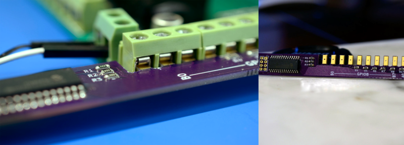
The unusual profile of [Andrew]’s board mates just right with the screw terminals, without adding any connectors or wiring to his bill of materials. Of course there is a trade-off between the cost of that extra PCB surface area and that of the wiring, but we can see the wiring getting out of control for someone like him with a reasonable number of relay boards to control.
We’ve featured PCB manufacture in all its facets here at Hackaday over the years. But it’s surprising how often the board is merely the substrate for the circuit. It’s worthwhile to be reminded once in a while that it too is a component, and unlike most others it is one you can endow with the features of your choice rather than having to rely on what can be found off-the-shelf.


OPTO-22 make 8 and 16 unit interface cards that interface on the low voltage side with a 50-pin header. I’ve done almost this exact same project for that form factor, but it uses a regular header connector instead of the finger PCB..
Oh wow, that’s neat! I have to keep this one in mind, it might come in handy someday.
Although it’s clever, especially for backward compatibility, this isn’t something that I would field.
Using proper edge connectors is the right way to go. It looks to me like the machine screws used in the terminal blocks will cut the copper traces pretty easily if they get torqued too much.
I’d coat them with solder before I screw them down, so that you have some thickness for the screws to bite into.
good idea, though. i like the novelty and will have to remember this. screw terms are common in some of my circles and a single mating ‘connector’ like that could be something to help idiot-proof connectivity.
Be aware that Lead free solder experiences “creep”. That means that if you clamp it down with a screw connection, over time the solder will flow out from under the pressure and the connection will become loose. This increases the contact resistance and might lead to intermittent problems.
regular solder does too, that is why you should never tin wires going into screw terminals. The board itself is also going to creep so it probably won’t be reliable over time
Never?!? Really. I’ve been doing it for nearly 30 years. I tinned every single stranded wire terminated to this type of block. My techs knew that not doing so was grounds for termination (no pun intended, really). I have graduated to bootlace ferrules, as they are quicker. Gas (butane) soldering irons have always been finicky, unreliable and are not well suited for air travel.
But I have no experience with creep. Ignorance is bliss. is there any information published on this topic? I know that in my case, the benefits outweighed the potential for creep, so I don’t really care.
@GYRE google “SnPb solder creep”, both JPL and MIT have published on this topic.
I had very baaaad experiences with tined wire and screw terminals, wires tend to get loose, specially in Industrial environments ( vibrations, temperature, etc)
Me, Never not once, but I have seen a lot of very shitty terminations and absolutely none of them were tinned. In my line of work, corrosion, lizards, ants and lightning presented more concerns for me than fucking solder creep. Part of our SOP was to tighten all connections (even the ones that were crimped) as we always had issues with factory terminations being loose.
The screws don’t bite into that surface, there’s a leaf there in the connectors shown. For those leafs, I wouldn’t want to coat gold with solder, kind of defeats the point of having the gold there.
Yeah i agree PCI type connectors are tried and tested and as long as you are not connecting/disconnecting on a daily basis will stand the test of time. Having said that it is still a novel idea.
The screws do not make contact with the copper pad. There is a piece of metal bent inside that moves up and down with the screw.
This is not transferring any significant amount of current and slow speed, so I wasn’t as worried about reliability.
It wouldn’t be a bad idea to throw 15A at it and see what happens.
It is a tight fit with just the copper. If you want to use solder, you would have to go with a half height board.
I would’nt change anything really, the connection will be best with no solder on the pads. The only thing that might lead to a shortened lifespan is mechanical stress in the pcbs as they are clamped together on so many points.
The screws don’t touch the copper, there is a metal finger between the screw and whatever you place inside.
Yeah, I do this card-edge thing to make test jigs for boards that have a bunch of these Phoenix-style screw connectors. I should probably move to pogo pins, but this works OK for now and is much faster than inserting 12 wires manually!
If you’re feeling super-hacky, note that most of these screw terminals are at 0.2″ pitch, which means you can make these edge-connectors from veroboard/stripboard and a dremel. The reinforced cutoff wheels are where it’s at for making the notches.
Nice tip! I will remember that for the next time I need something quickly in the workshop. Phoenix are expensive for prototyping.
They’re real cheap on eBay! I don’t think I’ve ever used a real Phoenix one, just the Chinese clones. Of course you need to take it on faith that they’re not lying about the plastics in use: is it *really* UL94V-0, etc.
Of course because the connectors are 0.2″ pitch, they themselves go great on a veroboard prototype.
This would be quite handy for stepper motor connections. Just run each finger out to a solder hole for the wires.
Or just buy the proper pluggable connectors, e.g. Phoenix 1757035 and whatever it plugs into, or the $0.30/ea eBay version. Molex Ultrafit are also nice, if you have control over the board layout.
“Molex Ultrafit, feels comfortable and protected” do they have wings also? xD
*rolls eyes*
they’re, uh, ribbed.
We used the same technique for an upgrade to an old device that needed a new interface option added to it. The space inside the metal-case was so tight that we did not have enough room to use a different connector and no mounting points to fix the new board onto. So we went with the option of clamping the new addon board with pcb-fingers in the screw terminals of the original circuit too. Has been field tested now for some years, and it seems to work very well.