We love little tricks like this. Suppose that you want to generate an IR remote’s signal. It’s easy, because most of the codes are known. But it can be slightly harder because most IR remotes and receivers modulate the on pulses with a square wave at roughly 38 kHz for background lighting immunity.
With a competent PWM generator on a microcontroller, you can create this carrier modulation easily enough yourself. Set the PWM frequency to 38 kHz and the duty cycle somewhere in the 33%-50% range, and you’re set. But what if you don’t have a competent PWM generator? Such was the case that prompted [AnalysIR Blog] to fake it, with USART.
Here’s the trick. You set up the serial port to communicate at ten times the desired carrier frequency, and then transmit “special” data. (The number ten comes from eight bits of data plus a start and a stop bit.) If you want a 50% duty cycle, you simply send 0b11110000, as fast as the microcontroller will allow, for a mark and nothing for a space.
There’s some extra detail with inverting the signal if, as most do, your USART idles high. But that’s really it. It’s a cute trick for when you’re desperate enough to need it. And if you’d like to brush up some more on your asynchronous serial skills, check out our guide on troubleshooting USART, and the great comments that ensued.


You can also use USART to bitbang 1-Wire. The bit length is quite critical, but bit spacing isn’t. This way you won’t need another interrupt on the micro.
rated H for hack.
Hmm… Sounds interesting except… 38Kx10 = 380K. Most traditional UARTs (and many new ones, in lower power) might not do. (Remember 115200 bit/sec max from a decade or two ago?) I was just wondering, why can’t we use 38400 bit/sec UART data rate and send 10101010 (with start mostly 0 and stop mostly 1, in case of reverse invert transmitting word to 01010101) UARTs have fairly good clock stability now a days. RS232 needs stability within 2% but most are better than 1%. I am sure IR receiver would be okay with that much variation?
@Abhi
The x10 approach allows you to generate a range of duty cycles(10-90% in 10% steps) vs only 10% & 50% when using x1 as in your comment. 30% or 40% would be more common for IR remote control. We used the approach you suggested initially, until we needed a different duty cycle.
As you move away from the nominal frequency of an IR receiver the performance/range decreases. Although 38400Hz vs 38000Hz would not be material in 99%+ of situations with a 38kHz receiver.
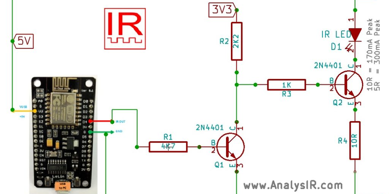
This post is focused on the ESP8266 NodeMCU, which AFAIK only supports PWM from 100Hz to 1,000kHz which is inadequate for IRremote control which primarily operates in the range of 30-58kHz.
I thought of the same solution, but you have to set the baud rate at 76,8kbit/s to get a carrier frequency of 36,4kHz. Which is really close enough to the nominal frequency, the selectivity is just some RC filters.
Of course, you are correct Martin…you would need to double the Baud rate(frequency) to achieve this modified approach.The ESP8266 doesn’t appear to be limited to ‘fixed/standard’ BAUD rates and can take arbitrary frequencies.
On AVRs we had to use a slightly different approach by leveraging the clock output pin from the Synchonous UART to get the full range of IR frequencies. On the Particle Photon it works similar to the ESP8266. This suggests that with a 16MHz system clock it may be difficult to use this approach for standard IR carrier frequencies, but with faster clocks, arbitrary fequencies should be achievable for IR signals. (Similar posts for AVRs/Arduinos & Photon are available on our blog). Again, I would only use these approaches if the required PWM was not natively available (ESP8266) or if all of the timers or PWM peripherals were occupied with other tasks.
@Martin, yeah probably I missed baudrate needs to be 2x (unless you go for Manchester/NRZ or something similar ;) but then space would be a problem and UART is not any of this either)
@AnalysIR I was not aware that PWM might be required for IR remote. But using UART for IR remote definitely is good hack. ( Not sure if Lirc/WinLirc also did some similar or not.)
@Abhi
The encoding you are referring to (e.g. RC5 & RC6) is related to the mark/space durations of the IR signal, not the carrier PWM – so not an issue.
Re LIRC: There are are a lot of different devices supporting LIRC, some over USB. Others do bit banging of the serial port control signals (like DTR) for rx at least.
A good site for IR remote control fundamentals is: http://www.sbprojects.com/knowledge/ir/
Cool, but why complicate things and use 2 transistors when a single PNP would do?
Because of hack!
Good point….because it is just a test circuit to generate the IR signals & I have a ‘very’ large bag of NPNs available. :)
It also serves to highlight that the output is inverted vs typical IR driver circuits.
The main idea is generating PWM for IR using a UART.
:)) Then buy a smaller bag of PNP transistors as well.
wut u no lik npn? (JK)
why not connect one side of the diode to UART/PWM for the carrier frequency, the the other side of the IR diode to a data pin, this way much easier to code. Same trick can be done if you want IR serial, then one side of IR diode to a PWN pin and the other side to serial TX :-) the little 3 pin IR receiver connects to a FTDI232 USB stick, and you now got wireless data, need to invert the date ? just swap the diode :-) no need for transistors, plenty of range in just the current drive from AVR pins directly to IR diode. that is a one part tx side solution folks.
Unfortunately, the ESP8266 has a max current of 12mA on IO pins which will not deliver much range with an IR LED. I did see some mentions online that it can sink more current on IO pins, but I could not find that in the datasheet.
However, it would be feasible to follow your suggestion on an AVR as the max current is up to 40mA(20 recommended) and this can get you a more usable range of operation. In all cases use of a current limiting resistor is advisable. see post via link below for more details:
https://www.analysir.com/blog/2014/10/03/driving-infrared-led-directly-arduino-pin/
You can also use UARTs as an extra timer when you run out…set up a TX empty interrupt, appropriate baud rate and bit count, and write a character to start the timer. A few milliseconds or microseconds later, interrupt!
Good idea Dave, for when it is needed :)
FYI: We have just posted a new blog article which now shows how to output IR from the ESP8266 NodeMCU in non-inverted mode usng a low level setting of the ESP8266 UART registers. (The first version could only provide an inverted IR output, which required additional circuitry)
.
Check out the blog post here ->
https://www.analysir.com/blog/2017/01/29/updated-esp8266-nodemcu-backdoor-upwm-hack-for-ir-signals/