At some point you’ve decided that you’re going to sell your wireless product (or any product with a clock that operates above 8kHz) in the United States. Good luck! You’re going to have to go through the FCC to get listed on the FCC OET EAS (Office of Engineering and Technology, Equipment Authorization System). Well… maybe.
As with everything FCC related, it’s very complicated, there are TLAs and confusing terms everywhere, and it will take you a lot longer than you’d like to figure out what it means for you. Whether you suffer through this, breeze by without a hitch, or never plan to subject yourself to this process, the FCC dance is an entertaining story so let’s dive in!
Did You Mean to Transmit that Signal?
There are two kinds of things that are getting tested; intentional radiators and unintentional radiators. Intentional means they are purposely putting out RF signals, like WiFi, Bluetooth, or any other transmitting radio. These must be tested and filed with the FCC before you can start selling or even marketing your product. Here you are looking at CFR 47 Part 15, Section 247 most likely.
Then there are unintentional radiators. This could be switching noise from a power supply, accidental antennas from poor ground pours, or long clock traces. You need to have your product tested for unintentional radiation (if you are an intentional transmitter you still have to have unintentional radiation testing as well), but you don’t necessarily need to have the reports sent to the FCC. Depending on the type of product, you will either need to do Verification (you don’t need an official testing lab and you keep the reports yourself in case you get asked), Declaration of Conformity (you need an official testing lab, but you keep the reports yourself in case you get asked), and Certification (in which you use an accredited testing lab and the FCC reviews the filed documents). The relevant part of the FCC guidelines is CFR 47, Part 15, Section 109.
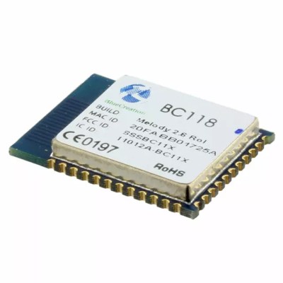
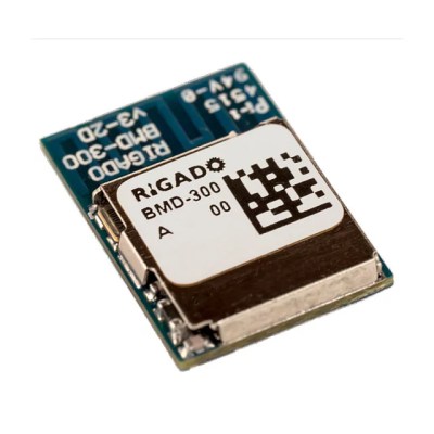
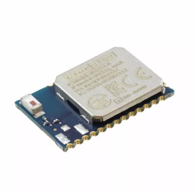
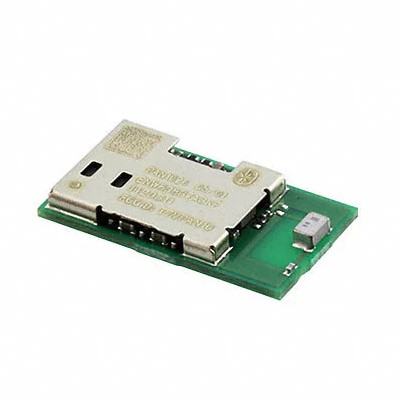
There’s another thing to consider, and that’s FCC Modular Approval. If you want to avoid all the hassle and expense of intentional emission testing, you can use a wireless module that has modular approval. There are lots of companies that make these modules for BLE, WiFi, Zigbee, GSM, and pretty much any wireless tech. They go through the painful FCC process for you and sell you their module, which has the chip, balun, antenna, crystal, and shield, all in a pretty package that you can solder onto your PCB. This will avoid the intentional emissions testing and give you an optimized transmitter. You’re still responsible for unintentional radiation on your full board, but this is much cheaper and easier and may not even need to be filed.
For low volumes of products, modules are a great way to jumpstart product development and start scaling up, and when you have proven the market and the economics make sense to switch (usually in the tens of thousands in volume), then you can go to your own design.
Get Into a Test Facility
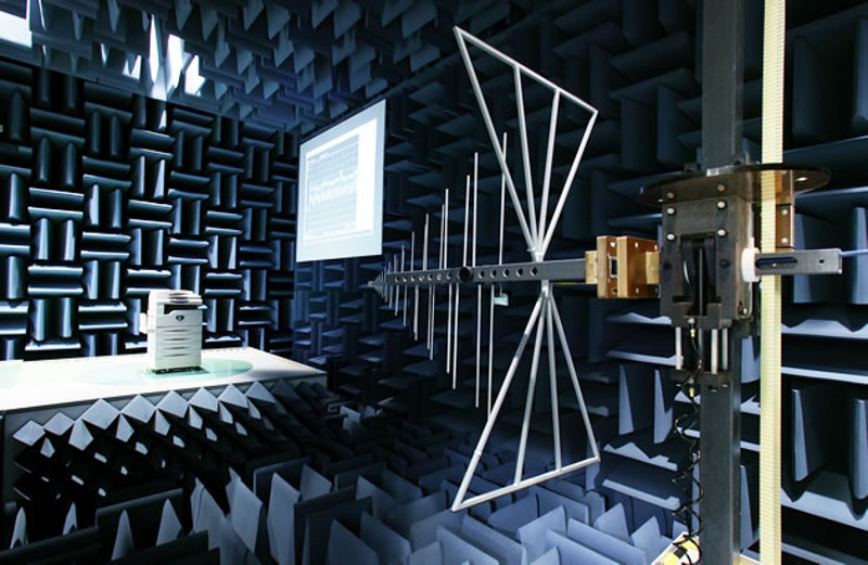
Let’s pretend you’re selling a WiFi toothbrush that records how long you’ve been brushing and uploads it to the cloud so that parents can hover over their children in yet another way. You’ll have to get your product tested for both Sections 109 and 247. The FCC doesn’t have their own testing facilities to do this; they accredit other testing facilities, and they’re located around the world. They even have a tool to help you find them.
Request quotes from a few test facilities as well as timelines for when they can get your product into their facility for testing. They will generally handle the filing after you fill out a few forms. Quotes for an intentional transmitter may contain sections for the following (rough ballpark numbers. your results may vary):
- CFR 47 Part 15 Section 247 – testing for intentional radiated emissions ~$5k
- CFR 47 Part 15 Section 109 – testing for unintentional radiated emissions ~$1k
- Test report documents ~$1k
- FCC Form 731 and some other filing paperwork ~$2k
- IC paperwork – $2k
What’s the IC? That’s Industry Canada, and if you want to sell in Canada, you have to jump through a couple extra hoops, but it’s better to do it at the same time than later and have to rerun the tests. Your test facility will help you navigate all the accounts you need to create and documents to file.
Do Your Homework
Once you’ve picked your facility, you need to prepare your Equipment Under Test (EUTs) and LOTS of documentation. The documentation can take a month or more to prepare and get settled. They want to know everything, including what the label is going to look like and how it will be affixed to the product permanently.
This prep work doesn’t end with the photos, user manual, Description of Operation, schematics, and block diagrams (the documents you see on the FCC EAS web site are a subset of the total number of documents prepared). You also have to prepare a test procedure document and make sure that your firmware is ready to handle all the strange modes you will have to put it in, and the other hardware you send (like any computers you install software on to control or reprogram the EUTs) is ready and easy to use. Time in the chamber is extremely expensive, and you want your testers to have as easy a time as possible and not need to contact you with a simple problem caused by an oversight.
A Test of Every Flavor
With the EUTs, they’re going to want to test in all possible configurations, so you’ll need to test your WiFi toothbrush when it’s running on battery, but also when it’s plugged in to the wall to charge. If you are including a charger, you’ll have to include the charger in the tests, even if it says it’s already FCC certified, because it’s the combination that you are selling which must meet the standards.
You’ll test it in normal operating mode, but also in continuously transmitting mode on every channel possible, so you’ll need to include firmware (or some way to control) which channel it is on and to put it in a special mode that allows for continuous transmission. Sometimes, manufacturers have made this a bit easier for you. For instance, if you are using a TI chip there is SmartRF Studio, which makes this really easy.
Fixing Your Oversteps
The FCC guidelines allow for certain powers at specific frequency ranges, so it’s possible that your device might be ever so slightly outside the range at the highest or lowest channel. You’ll either have to change the PCB, or you may be able to get away with writing firmware that limits the power at those extremes (you’ll have to have this tested), or write firmware that prevents the device from using those channels.
The testing facility will also want to measure output power directly, which means hooking up an SMA connector to the antenna. Lots of times your product won’t HAVE an SMA connector and will just pipe straight to a trace or chip antenna. This is where you get creative and cut the trace and airwire a short wire to an SMA connector that’s firmly glued to the PCB. It’s a hack, but it’s as close as you can get to being a good measure of the output power.
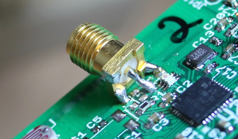
It’s not uncommon for a design to fail the first time. This sucks, but it’s not the end of the world. The testing facility may suspend tests, tell you what they think might be wrong, and let you fix it before continuing. You’ll often see space for extra passive components in the path between the transmitter and the antenna. These are for making whatever fine adjustments are necessary to get the PCB to be in compliance.
Practice Your Patience
A note from personal experience; stay engaged with your testing facility. I was unfortunate in that mine needed constant prodding, for a few months it wasn’t responding to email or phone calls, and from signing the contract to filing with the FCC was a whopping ten months. Usually you can expect it to take one or two, but as a little guy you may have to fight a little harder.
FCC testing can be intimidating, especially if it’s your first time. Testing facilities are accustomed to FCC virgins and will do some hand-holding, but a lot of the preparations are time consuming and need to be done by you. However, this certification is crucial in unlocking a huge market for your product. As with choosing the right components, case design, manufacturing process, and packagaing, FCC testing needs to be considered when planning product development timelines and throughout the design process.
[FCC testing image source: Some Hardware Guy]





Hello,
interesting article here, but i don’t fully understand it.
When i’m releasing a product that just needs verification, what is it that i must do?
it is cool that i don’t need a certified lab, but what do i need?
Otherwise, if i make a product that use a modular radio emitter that is certified, and if the rest of my board is “verification” level, i don’t need further testing, or is just it simpler?
Also, i heard of tricks to release products without doing a lot of certifications. Indeed, if i’m making a small, cheap product, in low volume, not for profit, i won’t have 5K$ to burn on certifications. So i heard that you can sell the product as a kit, and thus reduce the certifications required? It doesn’t mean that i want to escape regulations, but if i use no intentional radiators, or certified radio emitters, follow safe guidelines, for a small, hacker friendly to teach kids stuff about electronics, computing or robots, is it possible to have it as a kit to cut the hassle and provide it as a kit? IF so, what defines a kit? does it have to be soldered? or, on the extreme, if i provide it with a jumper that must be put in place to make it work, is still a kit? :)
I’m doing educational projects. If i can get orders from school directly, for sure, i’ll sell it at a good price and have all certifications. But for now, individual kids want the stuff, even if it’s a prototype, and for them i’d like to be able to sell it at parts cost.
The FCC defines a kit as (FCC 15.3):
“Any number of electronic parts, usually provided with a schematic diagram or printed circuit board, which, when assembled in accordance with instructions, results in a device subject to the regulations in this part, even if additional parts of any type are required to complete assembly.”
Here’s a blog post about it: http://www.emcfastpass.com/fcc-rules-kits-subassemblies/
What about Conformité Européenne?
Okay, it’s not the same as it’s self certification thing, but anyway I think you could have mentioned CE in the beginning or at the end.
Yeh, if you want to have fun, go for CE as well. All the emissions stuff of FCC, plus susceptibility, plus RoHS, plus an assortment of safety things that you may or may not need to do and even some test labs weren’t sure what to tell me to do or not do…
As far as I know, there is no equivalent of the FCC OET EAS list in the EU.
What’s is required in the EU is that the peoples legally responsible of the company that make the product sign a conformity declaration. Those peoples will in theory take the responsibility if there product is not in conformity with the regulation that apply to the product. The choice to do or not to do the different conformity testing is left to the company. If the company is confident enough that his product will pass some tests, he can sign a conformity declaration without actually making those tests. It’s legal but increase legal risks.
Most of the time the risks are pretty small anyway, like a mandatory recall. So going without tests is quite reasonable for small volume hobby stuff.
The declaration of conformity is only a part of the CE compliance process, you also need a technical file to prove your product is compliant with the regulations. this file must consists of drawings, schematics, data sheets, calculations, drawings and schematics to prove compliance with the directive.
The easiest way to do this is by sending your item to a test lab and ask them to test according to the applicable harmonized standard. The European counterpart of FCC are the EMC and RED directive (former R&TTE). Most RED and EMC EN-standards are identical to ETSI, CISPR or IEC standards also referred to in FCC. You are allowed to put together your own evidence of compliance but the question is if the authorities will accept if not using a notified body.
More info you can find here:
http://ec.europa.eu/growth/single-market/european-standards/harmonised-standards/
It’s worth remembering that the CE mark is not limited to electronics/electrical products. It’s a mark that basically says “this product complies with the European directives associated with this product”. The Declaration of Conformity being the written statement that backs the mark up.
So, if you were building, say, a CNC machine then in addition to the EMC testing to comply with the EMC directive there may also be a need for compliance with the low voltage, RoHS and machinery directives.
The thing is though that the directives only provide a top level framework for the requirements. They don’t tell you how to meet those requirements.
So, you can use any means that you like to do that. The normal approach would be to use one of the harmonised european standards. It’s compliance with the standards which will stipulate what testing is involved. However, it would be perfectly legitimate to use an alternate standard if meeting that meant the product met the requirements in the directive.
As the designer/producer, you’re expected to maintain a technical construction file that has all the documented evidence of how you’ve met the directives. That would also include any justification for using an alternate standard from a harmonised one i.e. “We didn’t use the harmonised standard X because we used Y instead, and this means it’s still ok because X=Y” or whatever.
Note that according to 47 CFR 15.103, lots of devices – particularly those dealt with by the Hackaday crowd – are exempt from testing and labeling requirements.
In particular, devices that are solely battery operated and aren’t clocked faster than 1.7 MHz are exempt (in particular, this exempts all of the 32 kHz clocked Vetinari clocks out there, including those – like mine – powered by boost converters). Devices that are solely used as industrial, commercial or medical test equipment are exempt (my own interpretation of this – IANAL, however – is that the stuff you build as testing gear on your bench is exempt, as are oscilloscopes and those sorts of devices). Devices used solely in a vehicle are exempt. Devices used as control system for appliances are exempt. There are a few more, but they’re more esoteric.
Boost converters also have a clock, just not an obvious one. And I bet it’s higher than 8kHz (don’t know where the 1.7MHz number comes from). Testing gear is not exempt, just tested to different standards.
Basically, ALMOST NOTHING is exempt. Hobbyists do a lot of mental gymnastics around this because of the high cost of certification but IMO everything so far has counted upon the FCC just not being interested in any kind of crackdown. And I doubt they will be in the future unless there is some massive complaint about a particular product interfering with people’s lives.
The 1.7 MHz number comes from 47 CFR 15.103(h). Go read it for yourself. Yes, boost converters have a clock – which is why I mentioned them – but not all of them run that fast.
You can assert otherwise, but you’ve provided no evidence.
And to clarify further… I said they were exempt from TESTING AND LABELLING requirements. Not from emissions standards.
http://transition.fcc.gov/eb/FieldNotices/ <—- Oh, they're interested, and crack-down quite hard. Check out some of the fines listed on that site. Huuuuuge fines.
Recently completed our first product with a cell modem. While the modem module is certified we still needed FCC Part 15 (unintentional radiator) plus output power and sensitivity testing to get on the Verizon network. We used a chip antenna and ran into trouble with the direct connection to the antenna required by the lab. We added a site for a u.fl connector on the board that we could connect with a 0 Ohm resistor when needed. Then we used a u.fl to SMA cable to provide a connection for the lab.
The problem was that with the connector circuit stuffed, the extra trace stub and the antenna matching circuit prevented us from getting the power output needed. Eventually got it working by removing all the matching components and cutting the trace to the antenna. If you are doing one of these with an on-board antenna I’d suggest looking at using a u.fl connector that sits right over the antenna signal path and has a built in switch so when nothing is connected the on-board antenna is used but when you plug a cable into the u.fl, the entire antenna circuit is disconnected.
Is a u.fl with a built-in switch an existing part? Surely you can’t populate it without adversely affecting the chip antenna?
I found this nugget of knowledge very interesting. I’ve used a bunch of modules that don’t have a footprint for an antenna connection — it’s too bad you can’t look up a picture of the actual EUTs for each filing. Would be fun to see who came up with the most creative solution.
Rosenberger makes a U.FL-like switching RF jack. I have personal experience with it. Other than add a little bit of inductance, it doesn’t adversely affect the chip antenna.
That said, my favorite technique for providing a jack for conducted emissions testing is the following, which several labs have “blessed” as a good technique. Put the pads for two chip resistors such that one of the ends overlap. This is your common point, to connect to your transmitter. Connect the antenna to one of the chip resistors. Put down a footprint for a U.Fl. jack and connect it to the other chip resistor. Normally, in production, you only populate the chip resistor connecting the transmitter to the antenna, and not the U.Fl. jack and the other resistor. For conducted emissions test, remove the resistor connecting the antenna, solder in the resistor connecting the U.Fl, and solder in the jack, and you’re ready for testing.
this is what the modders on this page love. when we can hook up our own antenna.
Backwoods Engineer – That was basically what we did, used a resistor to jump in the u.fl. At first we left the chip antenna connected and that didn’t work. Then cut the connection to the antenna and still did not work. Apparently the trace stub to the u.fl was the problem. RF is weird!
Not u.fl, but used these before (production/certification tests of RF interfaces) in products: http://www.murata.com/products/connector/switchconnector ; note the isolation in the “open” state is not infinite
Here’s an example: Amphenol RF’s 902-9049
Adding extra RF connectors that you don’t normally need into a production build seems like a large chunk of cost. Leave the footprint for the connector unpopulated and go for the resistor-junction option. (Or put a capacitor or inductor there, if you feel like tweaking the matching.)
Luke – Agreed, we didn’t want to put a connector on that would never use. I’ve cracked open a few devices and been surprised to see unused u.fl connectors though. For small quantity I’d consider it if it would reduce testing risk. We could have bought a lot of connectors with the $3k or so it cost us to retest. Not to mention the time wasted.
Interesting article. I do this for a living, and have taken dozens of intentional and unintentional radiators through emissions testing in my career, mostly for US & Canada, but some Europe and Mexico, as well. I have the war stories and the scars to prove it, and I’d be glad to help if someone had a specific question.
It is a costly venture, fraught with risk and potential schedule delays, to get a product certified for radiated emissions. If you possibly can, as the article suggests, use a modular pre-certified device as the intentional radiator in your product.
If you have to design an unintentional radiator, such as a computer or controller device, for use in the home environment, do everything you can– shielding, metal enclosure, good grounding practices, chokes on all electrical interfaces– to minimize radiation. That way, when you do travel to the test lab, you have the best chance possible of passing.
What is a good book or source of information on this topic and other compliance requirements? FCC, CE, UL, RoHS, etc?
EMC for Product Designers, by Tim Williams, http://isbn.nu/0750681705 . That took me from an ‘Art of Electronics’ level to being able to design confidently for EMC to FCC/CE etc. Should be on every engineer’s reading list.
I have also taken a couple of dozen products through unintentional radiation along with a few intentional ones with some IC and CE thrown in. I agree with Backwoods Engineer that it will save a lot of trouble, expense and time if you do the design properly at the start.
Put in extra filtering at every wire that attaches to your product even if you think you don’t need it. If this is a high volume product and every cent matters, bring your EUT with the filter parts unpopulated along with an assortment of different value parts. You can quickly put in some components to try to fix it. Ferrite and capacitors are your friends.
Remember that lab time will cost hundreds of dollars per hour. The extra $0.25 BOM cost for an overkill design will cost a lot less than a few hours trying to find a fix at the test lab along with a new board spin.
I also try to be present when they do the tests. You can answer questions and keep the test engineers from spinning their wheels (and burning up $) if they don’t understand something or there are problems.
+1
I also recommend doing a pre-scan as early as possible in the design process, when you get your first prototype in hand, well before you’re looking at commercial shipping.
Most people think the process is:
design->prototype->next prototype->next prototype->final prototype->FCC certification->shipping
This is a bad idea. I recommend:
design->prototype->FCC pre-scan->next prototype-> …
A pre-scan is MUCH cheaper. There is no need for a report, no IC (if FCC passes, IC is really not likely to fail), etc. You can be in and out of the lab in 2 hours for ~$500.
Accidentally pressed Report button. Finger slipped. Sorry.
I’d also add that being able to tweak the firmware for the DUT onsite at the pre-scan lab will save some time/money. If you’ve got an external clock pin that is on but not needed (i.e. not driving another IC on the board) than turn it off!
I was working on a board that had a nasty 625Mhz peak (above FCC unintentional radiation limits) which we were racking our brains to figure out where it was coming from. System clock was 800Mhz, LPDDR2 was running at 400MHz. We thought it might have been the LCD connector since we forgot to include chokes on the board for this rev of the board and those signals were toggling (and had a max clock speed of 125Mhz) even though we weren’t driving a monitor. We disabled the LCD signals in software but that didn’t fix it. Turns out that one of the internal clocks for the PCIe bus was enabled (and running at 125MHz). So were were getting noise from the 5th harmonic of that clock. Since we didn’t have a PCIe bus on this board we disabled that clock and the spike went away.
@Backwoods Engineer
Any chance of stories about those scars? I’m imagining the electronics equivalent to angering the gazebo.
Hi Backwoods Engineer,
Thank you very much for your kindness.
We understand that if we are to SELL a product, the product needs to be tested for section 109 if it is the unintentional radiator and it needs to be tested for both section 109 and 247 if it is the intentional one.
However, the regulations of open source product seem blurry at this moment. Our team aim to provide open source assistive technologies (AT) to help people with disabilities to use their AT devices more easily. Particularly, we are recently working on some AT switches project that will use MCUs and one of the switches will use a capacitive proximity sensor in it. Should we avoid using those chips that have clocks in them to get away of the FCC troubles even as open source provider?
If more information is needed to be provided for you to determine the possibilities, I am willing to do so.
Thank you!
I have passed the measurements neccessary for CE with several products.
I took the DUT to the test lab and operated it there myself while the test engineers did the measurements. This was very helpful, because I could fix small issues instantly. One product failed the ESD test first. With some tips from the test engineer I was able to do a small modification on site to the product that helped so the DUT passed when we redid the test half an hour later. This would never have been possible if I just sent the DUT to the test lab without being there during the test.
Also I learned quite a lot about EMC and EMC testing while talking to the test engineers and observing the little tricks they did during measurement.
So I recommend to actually go to the test lab and not just ship your DUT there. It can save you a lot of time and money.
And still, when I turn off the mains at home, the noicelevel drops from an S3 to a flat zero on my shortwawe radio.
I have been sorting out the worst wallwarts, I do not own a plasma-tv (AKA broadband transmitter) and I do not have any LED lights or dimmers.
Still, mobile chargers, laptop chargers and everything else connected all adds up.
I have invested a small fortune on ferrites and clip on ferrites, and I am down to a level where I can use my radio, until my neighbour turns on his plasma TV och the robot lawn mower, and he still lives 300yards away.
Li
I hope for your wallets sake that you actually bought low frequency ferrite cores, if not, they have basically no real effect in the shortwave range, because standard ferrites peak impedance is at 100MHz, and not between 2 and 30 MHz. And you should know that all these EMI regulations are not there to eliminate emission, they only put a limit on it.
I did buy ferrites for 2-30MHz, but since I use frequencys above 100MHz too, I added a few snap on ferrites too.
And I am well aware that they still might be within limits as sold, but I still think the limits are way to high.
The lawn mower might not be however since they had to stop selling a few models the didn’t meet the regulations.
Of course this one was sold before the ban, hopefully it all has the same china quality so it will die in a while.
There is alternative to all that hassle with testing. Just print on your device markings that are almost genuine FCC and CE. They will mean China Export and From Chinese Company. Then you export it from China to USA and EU and pray to deity of your choosing that no one will ever test it or check you in FCC or CE databases With the amount of shi… ekhm, shipments coming into USA and EU risk of being caught are pretty slim. And you can always claim that Chinese manufacturer promised to do all the testing and certification for you, and gave you this almost genuine documentation…
Playing chicken with the federal government is a high risk, high reward proposition.
This process can take a long time. I definitely recommend doing a pre-scan before you are at your final hardware, this will allow the opportunity to correct any issues without adding new hardware spins.
There are some brokerage-type services that can guide you through the process, handle all the paperwork and review your RF design. One company I’ve worked with is called Swift Labs. Personally I find it’s worth it to use a broker because they know the process already, can find the best (or cheapest) certified lab for your product and have the connections at those labs. Frankly getting all the required compliance certifications can be quite a headache, I prefer working on the next rev or product.
So what is the cheapest lab these days? It is quite frustrating they make it so difficult to operate one, given there are plenty of people who would love to run a single person oats and most of the tests are computer controlled so the test engineer pushes a button and walks away and all the test reports are templated. Make it cheap and easy to be certified and more of the Chinese products that are going to be in homes anyway will be compliant.
The cheapest lab is the one closest to home :) Minimize your travel time, develop a relationship with someone close-by and it will pay for itself.
I suggest going to a local IEEE meeting (especially if there is an IEEE-EMC group meeting) and ask around — I’m sure you’ll get lots of recommendations.
I think there should be a good market for the “single person OATS” doing un-certified pre-scan testing on the cheap. You’ll get 99% of the results and a good feeling that when you do take the product to an (expensive) certified site it will pass the first time.
Also look at local universities that have a decent “Radiation Lab”. I know both University of Michigan and Grand Valley State University have pre-compliance labs (UM, in fact, is actually FCC-certified).
Have you ever tryed to buy one of these GHz signal generators, 200W+ RF broadband power-amplifiers, broadband-antennas and EMI receivers? It’s not the engineer that pushes the button on a computer that is expensive, it’s everything that goes into a lab before the engineer can push a button that makes it expensive. You have to keep in mind that the tools are high end engineered, but for a very small market with very limited sales figures. So you usually talk way beyond 200k$ just for a basic RF immunity and emission equipment, and then you still need a shielded, anechoic chamber where you can measure your DUT.
I’d be interested to know what percentage of the items sold on Tindie have gone through any sort of certification. I’ve got a few projects that I think would be worth putting on there, but I’m not sure if doing so without having any certs (lowest clock frequency is 4M) is technically illegal.
I’m gonna bet that about 90% don’t, and 80% don’t even know that they legally have to get certified. Really, it’s not like the FCC is going around in vans listening for stray signals or buying up products just to test for compliance. That would cost money, something which I doubt they have a whole lot of relative to the number of products on the market today.
Actually, they really do just that: http://transition.fcc.gov/eb/FieldNotices/
…the late development stage, after which hardware guy realises that he should have listened to software guy’s concerns about noise and signal filtering, projects responsibility for enlisting those 14 Buck converters onto software guy, even though SG was not around at that stage to advise against it, and in a monumental fit of Napoleonic pathology, sacks software guy over the issue. – “My tiny ego is at no further threat…problem solved!”
Heh, many many moons ago, I got into something like that, fired the customer before they fired me. They asked advice on a new system, bought the one that was the worst of the bunch and I specifically told them to avoid like the plague, and they were pissed at me when it failed to meet expectations in the many ways I told them it would, as well as being outright flaky. Advised them to return it, while they had the option, because even a blind caveman could tell what a dog it was within the first month, but nope, emotionally committed or something, because as far as they could see, there was no problem with it, apart from all these major problems that they thought any fresh MCSE could snap their fingers to make go away. In addition to being inadequate, it had definite warrantiable issues, which I could see turning it doorstop dead real quickly, and they wouldn’t call distributor or manufacturer on it. After another tirade on how this was all my fault, I fired them… … Now I’ll admit when I’m wrong, it didn’t turn doorstop dead quite that quickly, it took exactly the span of remaining warranty, which was just a few months. Meanwhile they got in a willing to please PFY who turned grey before 30, trying to slap bandaids on machine gun victims as it were… he got fired when it died of course… got to yarn with him a couple of years later, in a field where time in field is super precious, he hides those few months on his resume. Turned out, that after a wasted year and suffering total loss of their investment on that, plus whatever all the functionality it didn’t achieve cost them, they bought exactly what I told them to in the first place. Then they were quite undeservedly happy ever after.
Great article, I am waiting for the CE version now!
I may need to have a product FCC tested soon. Are all FCC accredited testing facilities using the same rates? How do you choose one, apart from selecting by location?
Any good experiences/recommendation for particular testing facilities?