You might imagine that all one should need to operate a microscope would be a good set of eyes. Unfortunately if you are an amputee that may not be the case. Veterinary lab work for example requires control of focus, as well as the ability to move the sample in both X and Y directions, and these are not tasks that can easily be performed simultaneously with only a single hand.
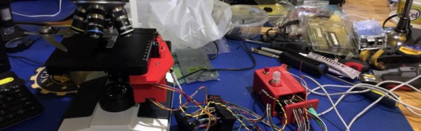
[ksk]’s solution to this problem is to use geared stepper motors and an Arduino Mega to allow the manual functions of the microscope to be controlled from a computer mouse or trackball. The motors are mounted on the microscope controls with a custom 3D-printed housing. A rotary selector on the control box containing the Arduino allows the user to select a slow or fast mode for fine or coarse adjustment.
It’s fair to say that this project is still a work in progress, we’re featuring it in our series of posts looking at Hackaday Prize entries. However judging by the progress reported so far it’s clear that this is a project with significant potential, and we can see the finished product could be of use to anyone operating the microscope.
How often do you think deeply about the products around you? How about those you owned five years ago? Ten? The Cicada — brainchild of [Daniel Kerris] — is an art piece that aims to have the observer reflect on consumer culture, buyer’s remorse, and wanting what we cannot have.
The Cicada consists of an ultrasonic sensor feeding data to a Raspberry pi which — calculating the distance of an approaching human — either speeds up or slows down a servo motor connected to a General Electric Walkman’s cassette speed potentiometer. Upon detecting someone approaching, The Cicada begins to loop the chorus of Celine Dion’s “I Will Always Love You”. As you move closer, the tape speed slows, and there is a transition from love at first sight to nightmarish drawl as the music slows.
[Pabr] is trying to make dry ice the hard way by building a thermoelectric dry ice generator. The project is a well planned round trip through thermodynamics and cryogenics with a hard landing on the icy grounds of trial and error.
[Pabr’s] four stage Peltier element on a heatsink.While dry ice can be obtained with simpler methods, for example by venting gaseous CO2 from fire extinguishers and collecting the forming CO2 flakes, [pabr’s] method is indeed attractive as a more compact solid-state solution. The setup employs a four stage Peltier element, which uses four Peltier stages to achieve a high temperature differential.
With sufficient cooling on the high-temperature side of the element, it should be well capable of achieving temperatures below -78.5 °C, the sublimation temperature of CO2. So far, [pabr] has built three different setups to expose small amounts of CO2 to the cold of the Peltier element, hoping to observe the formation of little dry ice flakes.
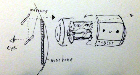
Part performance art and part social experiment, [mocymo]’s Smilemachine V6 helmet is as delightful as it is expressive. The helmet is made primarily from laser-cut MDF assembled around parts from a safety helmet. The display is an Android tablet with fine operation controlled by a Bluetooth mini keyboard, and the helmet cleverly makes use of the tablet’s ability to adjust the display to compensate for head tilt angle. It recently made an appearance at Maker Faire Tokyo, where the creator says the reception (especially by children) exceeded expectations.
There are several interesting things done with this device. One is the handheld controller, which is essentially a mini Bluetooth keyboard. To help allow fine control without needing to look down at the controller, the keyboard sits in a frame with some nuts and bolts used as highly tactile button extensions. By allowing the user to change the physical button layout (and setting up keyboard shortcuts on the device to match) the arrangement can be made more intuitive for the user. Some photos of this assembly are in the gallery after the break.
Geared mirrors to allow seeing out the front of the helmet.
Another interesting bit is that despite a tablet being right in front of your eyes, it is possible to see out the front of the helmet while wearing it. The solution is completely low-tech: two mirrors form a periscope whose angle can be adjusted by turning a knob on the side of the helmet.
Version 1 of the helmet was started back in 2012; this is version 6 and [mocymo] is already filling out a to-do list for refinements. The nose area is uncomfortable, the angle of periscope is slightly off and the gearing needs to be reworked, among other things. We can’t wait to see Version 7. Video and gallery are embedded below.
Most new houses are part of homeowners associations, covenants, or have other restrictions on the deed that dictate what color you can paint your house, the front door, or what type of mailbox is acceptable. For amateur radio operators, that means neighbors have the legal means to remove radio antennas, whether they’re unobtrusive 2 meter whips or gigantic moon bounce arrays. Antennas are ugly, HOAs claim, and drive down property values. Thousands of amateur radio operators have been silenced on the airwaves, simply because neighbors don’t like ugly antennas.
Now, this is about to change. The US House recently passed the Amateur Radio Parity Act (H.R. 1301) to amend the FCC’s Part 97 rules of amateur stations and private land-use restrictions.
The proposed amendment provides, ““Community associations should fairly administer private land-use regulations in the interest of their communities, while nevertheless permitting the installation and maintenance of effective outdoor Amateur Radio antennas.” This does not guarantee all antennas are allowed in communities governed by an HOA; the bill simply provides that antennas, ‘consistent with the aesthetic and physical characteristics of land and structures in community associations’ may be accommodated. While very few communities would allow a gigantic towers, C-band dishes, or 160 meters of coax strung up between trees, this bill will provide for small dipoles and inconspicuous antennae.
The full text of H.R. 1301 can be viewed on the ARRL site. The next step towards making this bill law is passage through the senate, and as always, visiting, calling, mailing, faxing, and emailing your senators (in that order) is the most effective way to make views heard.
Practically any combination of motor and gearbox can be mathematically arranged to fit all sorts of problems. You could lift a crane with a pager motor, it just might take a few hundred years. However, figuring out exactly what ratio you need can feel bit backwards the first time you have to do it.
A gear is nothing more than a clever way to make two circles rotate in concert with each other as if they were perfectly joined at their circumferences. Rather than relying on the friction between two rotating disks in contact, the designer instead relies on the strength of a gear tooth as the factor limiting the amount of torque that can be applied to the gear.
Everything is in gearing is neatly proportional. As long as your point of reference is correct, and some other stuff. Uh, it gets easier with practice.
Now as my physics professors taught me to do, let’s skip the semantics and spare ourselves some pedantics. Let us assume that all gears have a constant velocity when you’ve averaged it all out. Sure there is a perceptible difference between a perfect involute and a primitive lantern gear, but for the sake of discussion it doesn’t matter at all. Especially if you’re just going to 3D print the thing. Let’s say that they’re sitting on perfect bearings and friction isn’t a thing unless we make it so. Also we’ll go ahead and make them perfectly aligned, depthed, and toleranced.
Typically, a gearbox is used for two things. You have a smaller torque that you’d like to make into a bigger one or you have one rotational velocity that you’d like to exchange for another. Typically torque is represented with a capital or lowercase Tau (Ττ) and rotational velocity likes to have a lowercase omega (ω). It also doesn’t matter at all; it just makes your equations look cooler.
Now a lot of tutorials like to start with the idea of rolling a smaller circle against a bigger one. If the smaller circle is a third as large as the big one, it will take three rotations of the small circle to make the big one rotate twice. However, it is my opinion that thinking it in terms of the force applied allows a designer to think about the gearing more effectively.
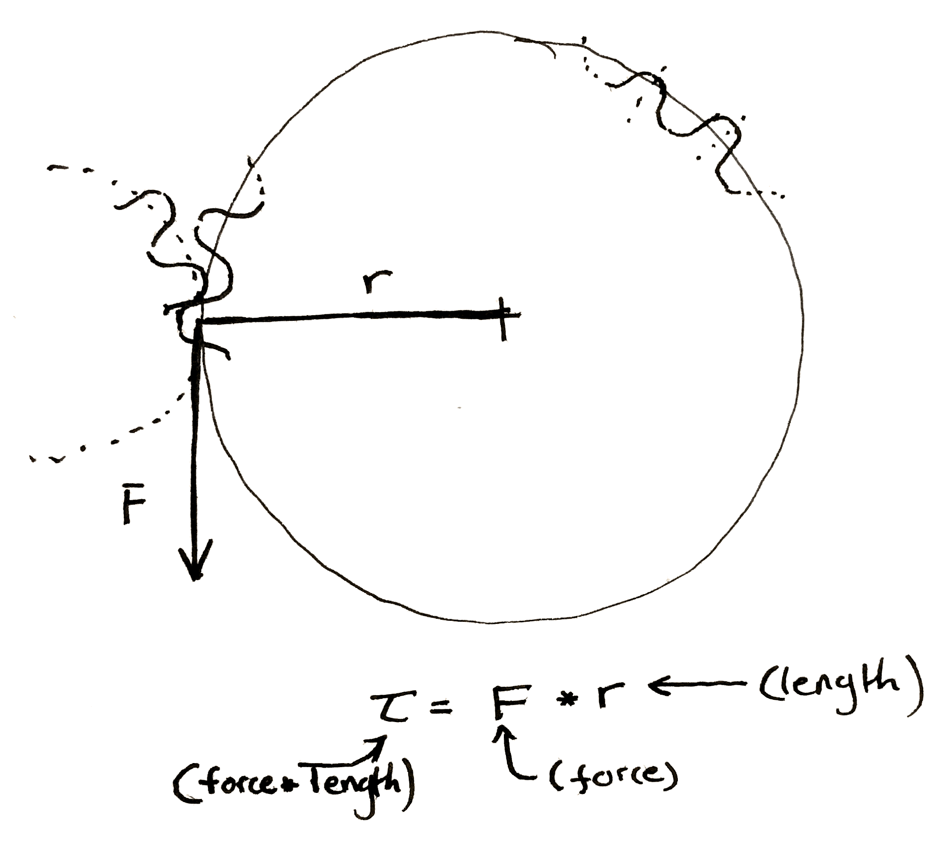
If the friction between the two surfaces of the circle is perfect, then any force applied tangentially to one of the circles will result in a perfectly perpendicular and equal force to the other circle at the point of contact between the two. Midway through writing the preceding sentence I began to understand why textbooks are so abstruse, so I also drew a picture. This results in two equations.
Now, when you have a force perpendicular to the line drawn to describe the radius, the equation for torque becomes really simple.
Multiply the length of the “lever arm”, “radius”, etc. by the force to get the preceding equations. Make sure to include the units.
You should end up force-unit * length-unit. Since I usually work in smaller gears I like to use N * mm. American websites typically use oz-in to rate motors. It is technically ozf-in (ounce-force), but the US customary system has a fetish for obtuseness.
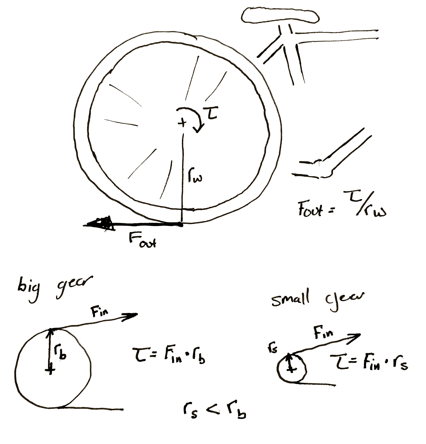
We can make some observations. The smaller gear always sees less torque at its center. This initially seemed a bit counter-intuitive to me. If I’m using a cheater bar to turn a bolt the longer I make the bar the more torque I can put on the bolt. So if I touch the outside of a really large gear I should be seeing a ton of torque at the center of a small gear rotating along with it. However, as we mentioned before, any torque applied on the outside of the larger gear is seen equal and tangential on the smaller. It’s as if you’re touching the outside of the small gear. The torque has to be smaller.
This is why you have to pedal so much harder when the rear sprocket on a bicycle gets smaller. Each time you make the sprocket smaller you shrink the torque input into the wheel. If the perpendicular output where the wheel hits the ground is <input from the small gear> / <radius of the wheel> then it’s obvious why this happens.
Hopefully my diagram doesn’t win a prize for awfulness. Then again, an award is an award. Remember that the bicycle wheel and its input gear are rigidly attached to each other.
It’s also important to note that any time you increase the torque, the speed of the gears slow by the same proportion. If you need 60 N*m out of a motor that can give 20 N*m and you use a 3:1 gearbox to do it. If the motor previously ran at 30 rpm it’s now running at 10 rpm.
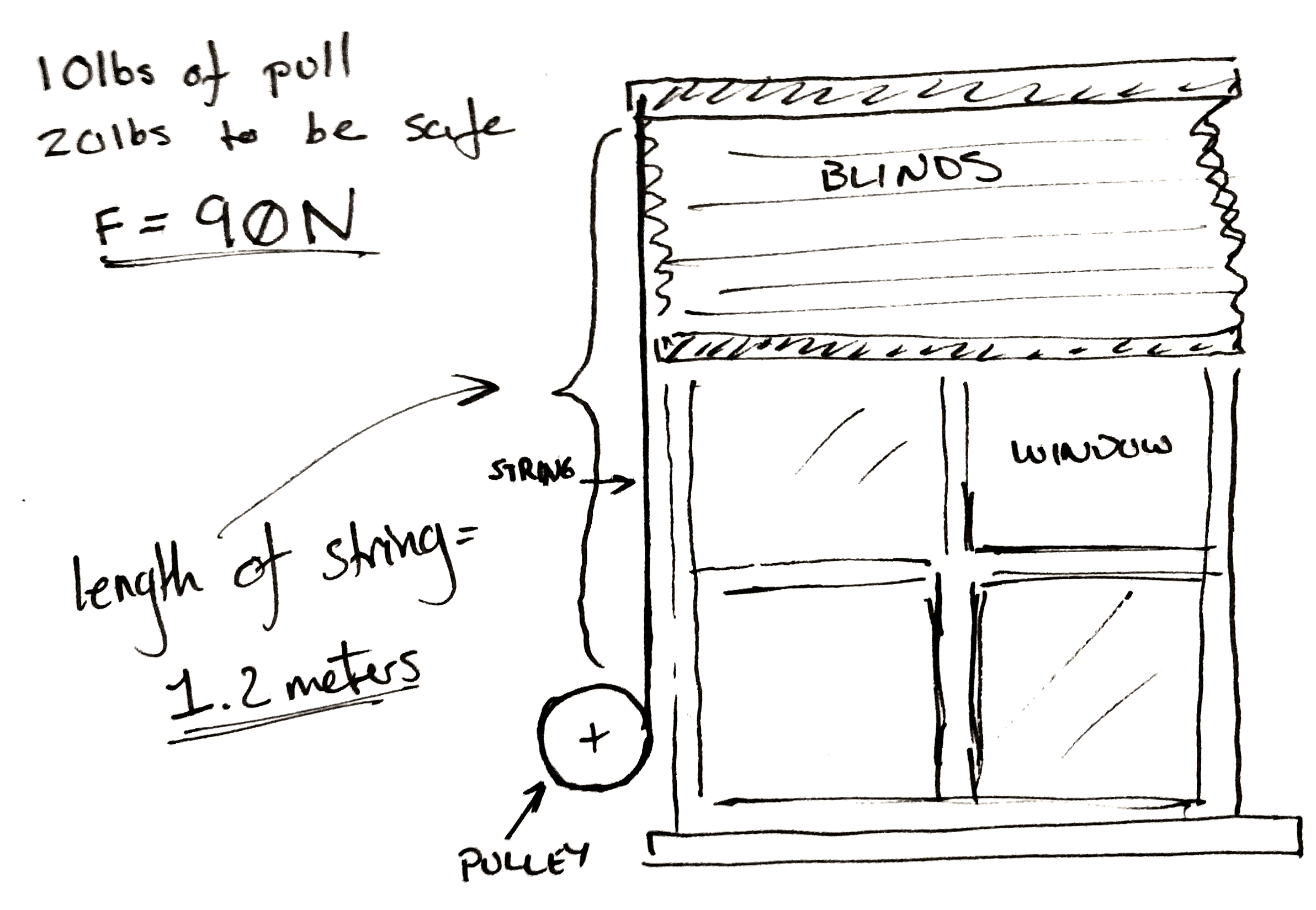
Let’s jump right into an example. Let’s say you want to make a device that automatically lifts your window blinds. You’ve got some junk and a 3D printer.
The problem set-up.
Now you’ve taken a spring scale and pulled until the shutter moves and you know you need 10 lbs. of pull to get the blinds to pull up. To make it easy on yourself you multiply this number by two so you know you need exactly 20 lbs of force to pull the curtain up. Then to make it really easy on yourself convert it all to Newtons. It’s approximately 90 N.
Now you don’t really care how fast the blinds pull up, but you go ahead and pull them up yourself. You get the feeling that the blinds won’t appreciate being lifted faster than the whole range in two seconds. You personally don’t care if takes ten seconds to, but you’d like it not to take too long.
You also measure the length of string pulled out to raise the blinds. It’s 1.2 meters.
A classic.
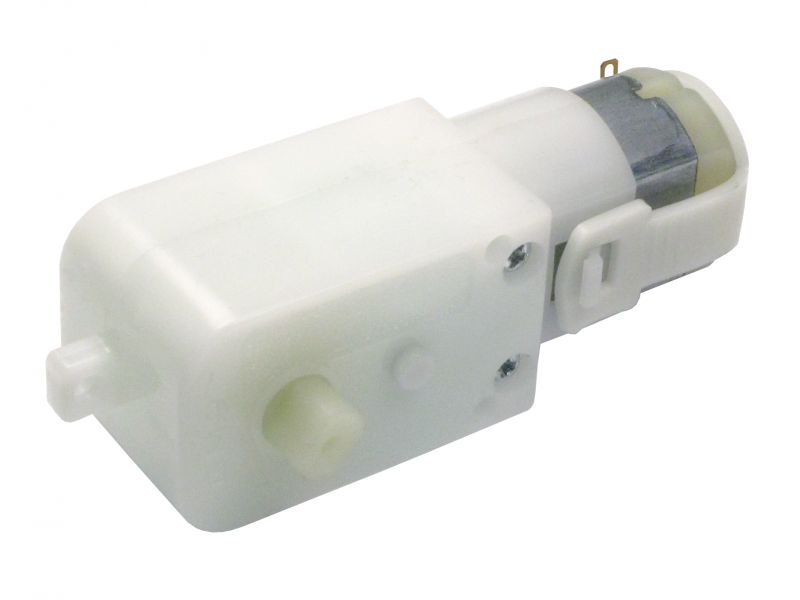
Lastly, you only have one spare power supply and a matching motor left in your entire laboratory after you followed the advice in a Hackaday article. Cursing the day the author was born, you sullenly write down the last specifications. You’ve got one of those cheap GM9 gear motors. 5 V, 66 rpm, and 300 N*mm. You damn him as you think fondly of your mountain of windshield washer motors and 80 lb server rack power supplies that you tossed out.
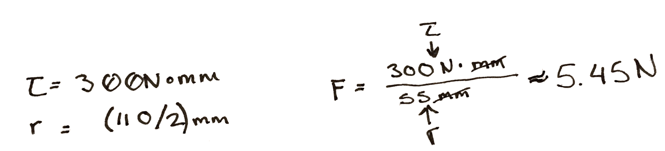
To start with, you do some experiments with a pulley. You arbitrarily pick, 3D print, and find that a 100 mm in diameter pulley seems to wind it up nicely by hand. By the end of the winding the outside diameter of the string is 110 mm. So you use the torque equations above. You find that at the end of the rotation, if you attach the motor directly, there is only 5.45 N of force being applied to the string. Not nearly enough.
Hrm..
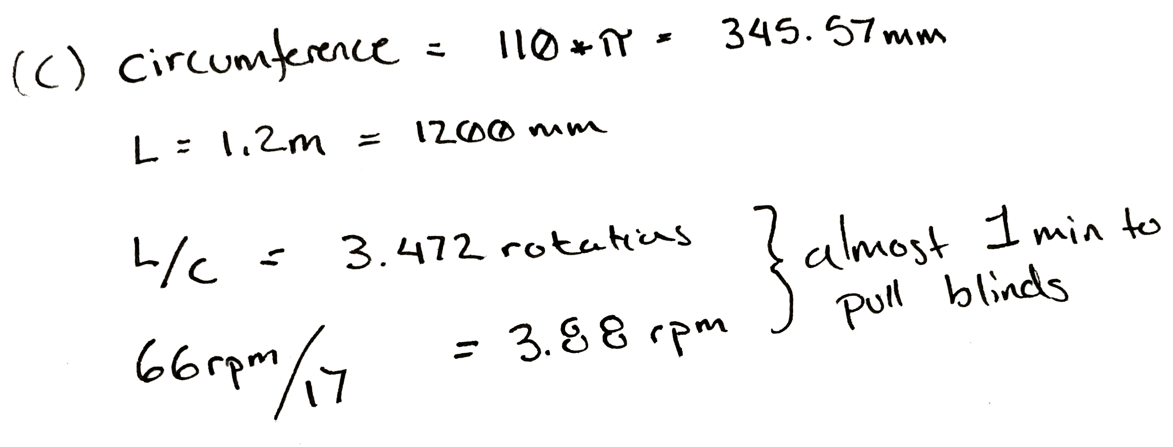
So, since you know everything is more or less proportional, you divide 90 N / 5.45 N, and arrive at an answer of 17. So, at a minimum for every turn of the pulley you need 17 turns of the motor to get the torque needed.
That would be okay, but it messes with our other specification. At a 17:1 ratio, it will take our 66 rpm motor pretty close to a minute to wind the blinds up.
Damn.
This is a moment for some pondering. Make a coffee. Maybe go write a relaxing comment to a Hackaday writer listing their various flaws, perceived and true, in excruciating detail.
What if you wound the string up on a closet rod? Those are only about 30 mm in diameter. You take a bit of rod and wind it up. It seems to work and since it’s wider the string only ends up adding 5 mm to the final diameter. You rework the calculation and find that in this case you only need a ratio of 6! Yes.
Now some of you who have done this before are likely gnashing your teeth, or more likely already down in the comments. Unfortunately it’s all proportional. While you only need a ratio of 6:1 now, nearly a third. You also need to rotate the pulley approximately three times as much to pull the same length of cord.
Sometimes you can’t win. In this case the only solution is to order a new motor. You look online for a bit and realize that one of the 12 V motors you threw away last week would work perfectly for this. You wouldn’t even need a gear box. You could attach it straight to the pulley. You look around your perfectly clean and orderly garage and feel empty.
However, just for fun you build a 6:1 gearbox anyway. It’s a hack after all.
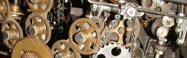
Cover photo of the hilariously complicated Do Nothing Machine credit to the Joe Martin Foundation.
We’ve seen a proliferation of real-life video game builds lately, but this one is a jaw-dropper! [Tomer Daniel] and his crew of twelve hackers, welders, and coders built a Space Invaders game for GeekCon 2016.
[Tomer] et al spent more time on the project than the writeup, so you’re going to have to content yourselves with the video, embedded below, and a raft of photos that they sent us. ([Tomer] wrote in and wanted to thank each of you, and his sponsors, by name, but that would be a couple paragraphs on its own. Condider yourselves all thanked!) Continue reading “Real-Life Space Invaders With Drones And Lasers”→


 Part performance art and part social experiment, [mocymo]’s