DC to DC conversion has come a long way. What was once took an electromechanical vibrator and transformer has been reduced to a PC board the size of a largish postage stamp that can be had for a couple of bucks on eBay. So why roll your own buck-boost converter for the ground up? Maybe because sometimes the best way to learn is by doing.
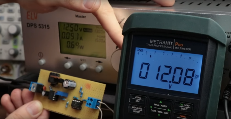
When it comes to clear and succinct explanations, [GreatScott!] has you covered. We recently reported on one of the videos from his Electronic Basics series, but the video below covers the slightly more advanced topic of DC-DC conversion in depth. [GreatScott!] describes how buck converters and boost converters work as separate entities, and how they can be integrated into a non-inverting buck-boost converter. He further simplifies that circuit into an inverting buck-boost, and sets about explaining the limitations of the circuit. With the addition of an op amp to provide feedback to control the duty cycle of the ATtiny85, the buck-boost overcomes its limitations and keeps a solid set point regardless of load or supply voltage.
If you’re looking to get into the theory of DC-DC conversion by putting it into practice, this is a great project to get you started. It’s also a good review for the old hands, as are most of [GreatScott!]’s videos. They’re worth checking out.


ya’ll should really just subscribe to his channel and just do an article about each video he puts out. it seems like everything he does is on here 3-7 days after it’s posted on youtube.
What was once took an electromechanical vibrator and transformer has been reduced to a PC board the size of a largish postage stamp that can be had for a couple of bucks on eBay.
The ones company I use to work for were just big transformers wired certain ways.
“just big transformers” ??? Without any extra circuitry, a transformer is always an AC to AC converter, and cannot ever be a DC to DC converter. It must have something extra, no matter what certain way it’s wired
Yes they were AC to AC. Big heavy things. Anything we had for DC to DC was a board (for the time) about the size of an open hand.
Sorry, but this is a bad way to go about this – doing this on a MC34063 is way better.
Not in a way that is not educational, but in a way that you are going to invite a whole lot of pain by doing it this way – perfboard, naive hysteretic control, weak mosfet drive, all kind of instability, current loops, but hey, at least his explanations are bang-on!
The MC34063A has hysteretic control.
A breadboard is a bad idea to learn about switching regulators, especially the higher speed ones.
Not to mention the EMI.
You can make a SMPS with microcontroller, and it will work just fine. Check out for example PIC16F785 and PIC12F1501. Microchip has few app notes on the subject. I wouldn’t recommend MC34063 for new designs, as there are better chips for doing this. MC34063 is a PFM controller and is best suited for constant load conditions…
Sure you can, but analyzing stability when it comes to digital control is whole new can of worms.
Better chips ? Such as ? I know there is a metric ton of them, but show me a chip that can do buck, boost, inverting, sepic with minimal external components and not fussy about the external components, easy to calculate and use. I’d very much like to see an improved version of MC34063, that goes to say 300kHz.
I’m not an expert in DC to DC converters, nor a handsome app note database. So you can google it, if you really need to. But because today I’m in a good mood, I did just that and found for example LT3758. You can do all mentio0ned topologies with PIC12F1501 (I actually did design a SEPIC converter for power LEDs with it, but didn’t have a chance to order some PCBs to build it). With PIC16F785 it’s even easier as it is basically parts of TL494 with microcontroller for configuring them. Also some people I respect claim that MC34063 datasheet and design formulae are wrong which makes it harder to use. I actually wanted to use it in one project, but after reading some discouraging posts I decided against it. There are better chips and better ways to do SMPS…
LT3758 is a great chip, but hey 5eu is 5eu, mc34063 is 50ct. Linear has a terrific selection, but it comes with a cost (and reliability).
I’d like to see that PIC try and drive a gate of a somewhat beefier MOSFET, also you’d need to program it, do current sensing, protection, supply it with power and do all kinds of stuff, and there is a thing with hangups and freezes – MCU should be equipped for contingencies like that, or need external drivers like UCD7100.
Regarding the formulas – IDK, I’ve done my own calculators in excel and it all turned out just fine, besides there is an online tool for that. MC34063 will work in any topology with a 100uH inductor and ~200pf timing cap, not perfectly but it will deliver and this makes it a perfect learning tool. I’ve done SEPIC, tapped boost, multipliers, dual supplies, LED drivers, it is a terrific chip.
PIC16F yeah no, I still have nightmares about the internal architecture of that thing, but thats just taste.
Digital power controllers are the future, but nothing beats plain on analog stuff here.
Lately I’ve stopped rolling my own SMPSs in favor of prebuilt modules – Murata, Recom, Aimtec, Meanwell and many many more – you just slap it on board and be done.
Better depends on the application.
There is likely nothing cheaper than the MC34063A, and it’s fundamental frequency is likely to be less than 150kHz since it is using bipolar transistors.
That ought to make EMI much easier to deal with. Use a shielded inductor and tight PCB layout and you’re good to go.
The 785 is notorious in this application, don’t use it for this, use a better replacement like the 16F17xx series that doesn’t have the same hardware bugs.
Core independent peripherals make this an attractive option, this is where the PIC and PSoC shine.
Now your power supply voltage regulator can report back it’s status over I2C / uart since the microcontroller has access to the entire control loop.
However, remember that the input offset voltage in the built-in microcontroller op amps is a factor, as is its slew rate. In peak current mode control designs this means the peak current will be larger than expected.
Depending on software for safety is a can of worms.
For hobbyists, add hardware fail-safe belt and suspenders.
I would like to see more about piezoelectric transformers, they are in a league all their own.
I did this a few years back with a 555 and a couple of comparators and a fet … i really needed one and could not wait for shipping xP
If you are making a current source, and you don’t care about switching frequency you don’t even need the 555.
VL = L * dI / dT.
VL = input voltage – output voltage.
L is your inductor value in henries.
dI is the peak current reached to terminate a switching cycle.
duty cycle will be fixed at 50%.
dT = the time it takes for the inductor to go from the lower current bound to the upper current bound.
As Vin goes up or down, dI/dT will change, changing the switching frequency.
You just need comparators and an RS latch… or just more comparators.
God damn this I looked at the link was thinking oh Ended up on a GS video the month where he built Buck buck.