[Alan Yates] is a hacker’s engineer. His job at Valve has been to help them figure out the hardware that makes virtual reality (VR) a real reality. And he invented a device that’s clever enough that it really should work, but difficult enough that it wasn’t straightforward how to make it work.
In his presentation at the Hackaday Supercon 2016, he walked us through all of the design and engineering challenges that were eventually conquered in getting the Lighthouse to market. We’re still a bit overwhelmed by the conceptual elegance of the device, so it’s nice to have the behind-the-scenes details as well.
Tracking is Hard
Figuring out where the viewer’s head is located (and oriented) in a room is an old problem for VR, and there have been a number of solutions in the last few decades.
 Lighthouse is very clever. It uses a few beacons placed inside the room that paint the room with IR light. From these signals, any receiver in the room can tell where it’s located by triangulation. The fundamental idea is that instead of measuring angles, which is hard to do with sufficient precision, the Lighthouse system reflects IR beams off of spinning mirrors inside the beacons — hence the name — which effectively turns the problem of measuring angles into one of keeping the rotation rate very constant and measuring time differences.
 There’s a room-wide flash for synchronization, and then two beams sweep in the X and Y directions across the room. From the time difference between the flash and the sweeps, a microcontroller and a photodiode, plus some trigonometry, is all you’d need to tell where the receiving device is. No network communication, no centralized server, no nothing; the simple passive detection of the sweeps does most of the work.
And we say most. The sweeps don’t come as often as you’d like. Most systems using Lighthouse also have an inertial measurement unit (IMU) with an accelerometer and a gyro. The IMU takes care of high frequency movements, and is disciplined by the less frequent Lighthouse updates. Combined, the system has very fast response as well as long-term accuracy.
Spinning
Imagine that you wanted to tell where something was located to within 1 mm at a range of 5 m. That gives you an angle of 200 microradians: the same angle subtended by the width of a piece of typing paper held out at arm’s length! Yeah. Worse: to get range information from the triangulation procedure, they needed four times that much angular resolution. Turned into a time, based on a 60 Hz spinning cylinder, that boils down to measuring times to within one cycle of a 48 MHz clock tick. No problem for a microcontroller.
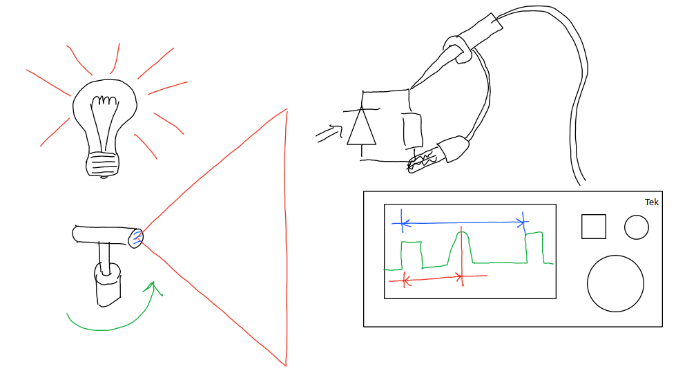
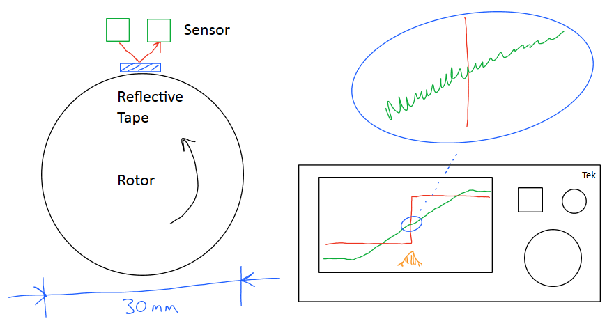 But making sure that the rotating mirror spins at a constant rate to that same degree of precision is difficult. They used an optical reflective sensor that is extremely thin: 94 nanometers. Then there’s the motor control system that processes this information. They got it working well enough to come around to the same position to within 2,500 atoms(!) using a piece of aluminum tape on a plastic rotor, with some fancy fluid-dynamic bearing motors from hard drives.
Then there’s the receiving end. They couldn’t use ridiculously strong laser beams for the sweeps, so there’s 120 dB of analog gain, with some signal conditioning going along the way. The beam sweeps by the sensor at about Mach 5, and the sensor, a normal old BPW34, is only a few millimeters wide.
Lighthouse Fails
The path to Lighthouse’s success looks a little bit like the floor of our office — strewn with failed prototypes, half-baked ideas made material, and lead-filled trial balloons. Things that you might expect to work, like a nice fancy ball-bearing motor, turn out to have to much friction and glitch irregularly.
 Even with their fancy fluid bearing motors, there are periods where everything’s running well, and then periods where everything goes wrong. Part of the challenge in the project was measuring all of these errors down to the few parts per million. They ended up calibrating and correcting on the fly.
To build a prototype, they started off with laser line elements from eBay. And they worked fine for the crappy proof of concept, but simply aren’t built to the specs that Valve needed for a high-performing product. Further, they were about to order hundreds of thousands of each piece — they needed to assure this same quality over the length of a long production run. And that’s without considering heat or lifetime of the laser.
 Sourcing lenses wasn’t any better. They ordered them from one firm that shipped them a bag of 10,000 loose lenses that arrived, naturally, scratched. The next manufacturer sent them three different kinds of lenses, sold under one SKU. In the end, they ended up making their own lenses because they needed to.
Open Problems
[Alan]’s talk was remarkably frank. It was like he was speaking to a technically-minded audience who cared about the way things work. (He was.) And that means that he got to dive into not only the fails and stumbling blocks, but even the dark corners of the design where there’s still room for improvement.
The optical sync is still an open issue, for instance. Although fiendishly clever, it’s probably the limiting factor in expanding the system to larger rooms; it uses a peak 50 W per blink. The length of time that the sync beam requires slows the overall system down as well. The sensors can’t react to the sweeps while they’re still blinded by the sync. Is there an RF / light hybrid in our future?
The photodiodes used are big, for increased sensitivity, but they’re off-the-shelf parts. Because they need to see each beacon in the room, there are many of them. These two facts create a design challenge for making smaller tracking devices.
With all of the research blood, sweat, and tears expended on the mechanical motor system, [Alan] suggests that maybe a MEMS or some other electro-optical path to making the sweeping beams might be an improvement, if it can be made to work with the same degree of resolution, that is.
The distance from the sensors is triangulated, based entirely on angles. If it were also possible to add a time-of-flight measurement component to the sweeping lasers, that would make 3D localization that much easier.
License to Hack
At the end of the talk, [Alan] pointed out that the Triad Semiconductor will sell you an ASIC on a breakout board that will greatly simplify creation of your own Lighthouse-enabled device. HTC, the company that sells the whole system, will sell you the beacons singly if you don’t want the entire VR experience. This is a very open and hackable technology.
Indeed, as [CNLohr] was working on reverse engineering the protocol that one of the HTC Vive controllers uses, none other than [Alan Yates] himself stopped by to offer him hints, without dropping any spoilers. Now that’s hacker-friendly.


completely over engineered. Simply use becons that send digital info on the IR. works well for the IR headsets from the 90’s
We all know how well those worked. You stood in a pod and got sick because the tracking was ever so slightly off. I think the point of this is to get as accurate positioning as possible to avoid the vertigo feeling.
Similar to Tim’s thoughts, I was also thinking about removing the need for a flash by ramping the Frequency sweep modulation of the light beam to key a high speed PLL trip signal to sync the beam positions in a way similar way to Doppler Radar. Maybe set the down converted modulation as the numeric angle (encoded in base 2 for direct mcu latch out on carrier loss), shifted left 2 decimal places for no fpu, and shift the Y/X axis to different modulation bands so they each give absolute position data (i.e. the decoder gives the angles for both axis, with one axis offset by 4k or so).
I suspect there are some IRDA and Fibre optic i/o transceiver amps around that can handle the task just fine.
The receiver would require a minimum of 3 optical receivers, 3 hf amps, 6 AFE detectors, and a $5 SoC.
Also, rotational imperfections may be filtered by controlling the modulation encoding for a know position, as with a cheap rotary encoder you can fudge the position correction prior to latch out as the laser scans past.
Now give Tim something cool… its Christmas ;-)
Sending angle information on the beam itself is an obvious way to replace optical sync emissions. The difficulty is doing that with sufficient precision without adding too much cost to the sensor system. You run into the radar resolution equation with simple FM techniques, obviously direct digital or convolutional approaches that work like pulse-compression techniques are an improvement. The baseband bandwidth and power consumption of the sensor AFEs and processing system can rise pretty sharply though.
So, at around 5m with 1mm granularity it is about 5000 discreet positions.
We apply minimal 2X over-sampling to the axis signals for a 20kHz bandwidth cost.
Or 24kHz with a 4k separation between signal sources.
The SA605D ($2.95 in 24h) supports up to 500MHz, and has 30Kz bandwidth with cheap ceramic filters.
Its older than me, and includes pretty much everything you need to test if it will work.
Accordingly, the initial part of the chirp keys the PLL lock-on, and the final signal period gives the encoded linear approximation of the angle. With simple parallel fpga counters we latch in a time-stamp from a global central clock, calculate the fundamental signal period estimates, and thus derive the event phase mismatch for orientation given the close proximity of the sample points. Since the sweep range is explicitly separated, than the threshold auto-latches the axis sample into the appropriate buffer after correcting the 4096Hz angle offset constant. When at least 6 signal locks occur without a timer roll over, than the axis triangulated-position & pose samples can be latched into a pipelined low-pass filter etc.
Note, that since a fast fpga is able to calculate phase mismatch far beyond the accuracy of the ceramic filters, than we are left with less than 5% absolute position drift error over time. Or roughly +- 0.5 discreet positions required to be perceived as stable.
And finally we arrive at:
3 surfaces * 3 sample points * $1.5 optics * $5 signal processing = $58.5 + support silicon
YMMV, as I did this Gedankenexperiment after a few German beers ;-)
Shut the fuck up. If it was so easy and cheap, where is your entry into the market? inb4 too cool for that inb4 autism inb4 armchair engineers
They should hand the problem over to people who are as skilled as Alan, but who do not have his skill set.
All that effort on a doomed idea. True ‘sunk cost’ fallacy in action.
Are you calling Lighthouse a failure or VR a failure?
fite me
Pefectly linearized angular determination. Literally tens of times more accurate than camera-based systems. Extreme beacon scalability. There is nothing anywhere close to lighthouse tech.
“The photodiodes used are big, for increased sensitivity, but they’re off-the-shelf parts. Because they need to see each beacon in the room, there are many of them. These two facts create a design challenge for making smaller tracking devices.”
Something like the eye of a fly design.
“The distance from the sensors is triangulated, based entirely on angles. If it were also possible to add a time-of-flight measurement component to the sweeping lasers, that would make 3D localization that much easier.”
Miniature atomic clocks.
Have the headset beacon back when it’s struck? A different wave length or signal for each beacon.
Each headset would be slightly different in the exact response delay, but ideally it would be consistent enough.
That’s what I first thought. 4 cubes labeled left/right front/back. The headset knows which is which and they transmit from a high precision oscillator synced through wifi. Mini GPS triangulation. Hell…put speakers in them and provide 3D positional sound as well.
Hackaday is starting to give me the same feeling of dread as YouTube… “Ah, this is some good information. I feel alright, glad I showed up. Now, don’t scroll to the comments… don’t scroll to the comments… ah sh*t, now I’m sad.”
https://chrome.google.com/webstore/detail/herp-derp-for-youtube/ioomnmgjblnnolpdgdhebainmfbipjoh
https://addons.mozilla.org/en-US/firefox/addon/herp-derp-for-youtube/
Just block all youtube cookies. You also get rid of the “privacy reminder” that jumps at your face every five videos.
I dont have this – perhaps as a result of using an adblocker.
Same here… Couple of really ignorant comments right off the bat. I see Dr. Yates has already responded to more intelligent posts in this thread. I will avoid responding to him directly as I quietly put forth that this is one of the best presentations I have seen in a long time. Such a humble person who has obviously evolved far beyond “hardware hacker” a long time ago. I say this as someone who has been doing complex RF designs for almost 2 decades and also as someone who actually has an HTC Vive (that works quite well). Please, more like this.
Keep on scrolling. The negative Nancys got in early on this thread. It gets constructive/intelligent below.
Wonder if pairing to a Kinect/Wii style IR disco grid would be any simpler on the processing side. Obviously patents and such get in the way of this.
A trilateration solution would mechanically be simpler but processing goes up, assuming we’re again using light/radio as the locating signal. Though it would allow one to use a larger volume with fewer beacons.
All of these light systems are cool but the real fun comes in when there’s an augmented reality solution. Paintball barricades or theater style props that the user can rearrange at will. This would get expensive quick with the current solutions as you’d need multiple beacons for each room. WiFi or BTLE would get around wall concerns, but then you’re blasting RF all over the place which may cause issues and almost certainly increases processing requirements.
Spinning line leaves a lot of space. I’ve not watched the video yet, but I’m reminded of radar codes. When you have done the pattern matching to find the range, most of the changes to that are fairly small and it makes sense to have a lot of edges in the detected signal. I wonder how easy it would be to spin a complicated blizzard of lines, polygonal mirror arrangement maybe.
At the level of accuracy which they have, a polygonal mirror would be very expensive to make.
It would probably be easier to add a second laser into the beam path (by using a phase splitter cube) and use that to generate the additional lines. However that would put a lot more demand on the detector part, possibly even needing additional sensors, because unlike radar, with IR you have a lot of interference.
Yep, you can totally do that, and I’ve talked about such approaches before. Power requirements increase because you are emitting more than just a single plane of light. Lighthouse was derived from more parallel emission systems and plenty of low cross-correlation coding techniques (both spatial and temporal) was investigated. The cost/performance ratio and complexity vrs time to market prevent doing such things in the first version, but it is by no means precluded in future versions.
Polygonal mirrors have scan angle limitations and non-linear angle/time sweeps. Nothing that can’t be engineered out of course, but again more complexity, cost, size, mass, power, etc. The very first drawing of a Lighthouse-like system I made was polygonal scanner and it worked more like radar with passive targets, or actively interrogated sensors that answered back to the base. The desire to decentralise computation in the system to improve its scalability and privacy drove me away from approaches where the base station needs to know anything about the tracked objects.
Did you try to implement a fixed angle dual fan system? After watching the video I’m now wondering if I’m going to hit a tech brick wall you already encountered:
https://hackaday.io/project/14977-room-based-vr-positioning
If you’ve not tried it… Will you please? :-D :-D
After so long, I really want to see if the principle has merit. I actually seriously considered flying over to the states to the conference to see your presentation and quiz you about my idea.
Yes, our latest design is a “vee beam” scanner like those altitude determining radar systems from just after WW2. It uses two beams on the one rotor, each with tilts in the opposite sense. This is a bit different to what you are describing I think, which has two beams but not inclined with respect to the axis of rotation? The main technical difficulties are a loss of field of view associated with tilting the fan beams and the increased sensitivity to manufacturing tolerances.
Another “Lighthouse-style” system I modelled uses non-radial beams. It does not require sync in some implementations and can give range information with less sensors, but requires very large rotors for baseline. It might be fun to build it in 2D and use it for a turtle robot or something similar constrained to move in a plane. That said Lighthouse of the style used with Steam VR but applied in 2D is very simple, one rotor 3 sensors gives you a 2D pose for planar navigation. I’ve found DC brushless motors make an easy rotor assembly for hacky Lighthouse experiments. For example you can just 3D print an optics mount assembly like this: https://twitter.com/vk2zay/status/761353466010738688
Yet another alternative 2D robotics navigation approach is to use Vive base stations mounted in the corners of the room but constrain the solver to operate only in a plane where the sensors on your robots move. Each base station gives you two angle measurements per sensor and it is possible to construct a transform from the azimuth-elevation measurements from a base into x-y positions in the plane. The trick is how to calibrate this system and solve for the pose of the plane in the base station coordinate system. Originally I was going to present the construction of this particular problem as “homework” for the Hackaday presentation, but it got cut for time. It is quite practical and useful right now to robotics hackers, so I mention it here and perhaps someone will attack it. It is not especially difficult to do if you use a simplified model of the base station which is probably good enough for many applications.
Heh, that’s quite cool. You’d still need to have precisely syncronised motors but in theory, depending on the steepness of the V, you should still be able to get an x/y bearing to each sensor. Very cool.
My idea traded the sync (I say traded, but that implies that I had a sync at one point – not true) and absolute rotational speed, for an absolute angle and just relative angular measurements.
Oh…. create the optics for a V with a disecting line and you’d be able to have absolute postioning but the potental for variable rotational speeds determined on the fly by the sensor!
Or… An “N’ shape for best of both worlds by determining the position in a single sweep regardless of rotational speed.
Since reading this, I’ve been wondering about how one could implement a “blizzard of lines” into a system (okay, more because I like the term).
I was wondering that, if each scan wasn’t just a single line but a pair of lines with each lighthouse scan path having a different inter-line spacing (so for two lighthouses you’d have 4 different scan line pair gaps), you could determine which scan line was being detected. This could allow multiple scans to occur simultaneously by watching for valid timings between pulse receptions and, if the scan speeds were slightly different, it would alleviate any static points being in ‘dead’ spots where scans collided in 3D space by constantly moving them. Effectively you’d be scanning a simplified projected-barcode across the room.
https://hackaday.io/project/14977-room-based-vr-positioning
:)
I guess I was thinking of something a lot simpler as I wasn’t inferring anything from the time between the two lines beyond using them as an identifier. More of a step up from the current lighthouse system rather than, what I read from the IO page, something that makes meaningful inferences from the two scans and multiple sensors
Great presentation, loved it!
“Figuring out where the viewer’s head is located (and oriented) in a room is an old problem for VR, and there have been a number of solutions in the last few decades.”
I think a future article should look at how Microsoft’s HoloLens deals with the problem.
Yes please. I haven’t tried a Vive but we do a bit of Hololens stuff here where I work, and the tracking and stability on them seems pretty good.
Doesn’t hololens simply look at objects in the room with a camera and use those as a reference never bothering with any absolute positioning?
Interesting modern take on a very old technology. I hope some HaD readers might find this interesting: https://en.wikipedia.org/wiki/VHF_omnidirectional_range
Short explanation:
Airplanes have navigated using a similar tech (VORs) for decades. It’s the same concept, but with a directional radio. There’s a narrow beam that sweeps a full 360*. Then there’s a “pulse” beacon when the beam is pointed due north. The relative delay between the two pulses (i.e. the pulse from the omni-directional beacon and the pulse as the steered beam sweeps past) allows a simple radio receiver to determine the angle of the receiver relative to the beacon. I.e. if you see the steered beam at 25% of the delay, you’re due East, 50% you’re due South, etc. Once you know the position of two beacons and your relative angle to them, you can triangulate your position.
That was a phase modulation based system and relied on the aircraft recieving and comparing both signals. You got the accuracy because it was pure analogue, and because the signal was, comparatively, available for a while.
It would be very near impossible to encode sub mrad resolution of phase detection into sensors small enough to be used in a VR headset and still make it cheap enough to be viable.
Right, and that’s exactly what they did. As the video showed, they measured the timing of the pulses (and compensated for all the errors) precisely enough to discriminate phase information and measure angle precisely enough (he mentioned 200u Radians, but I’m not sure if that was an arbitrary example number or realistic) for their needs.
While conscious of the post near the top of the thread about trolling, I still have to disagree; the systems are based on completely different principles.
Lighthouse has an initial pulse and laser sweep timed to start on that pulse with a very accurately fixed rotational speed. The time between the pulse and the laser hitting gives the angle.
VORs use two signals constantly with one being swept and its signal phase being changed wrt to angle it is pointing and the device measuring the angle by comparing the two signals at the time it receives both. Rotational speed is irrelevant for VORs, indeed if the base were constantly pointing at the target rather than sweeping the target would always be able to determine its bearing.
You take me back to my days serving in the RAAF.
The beacon this reminded of was the “TACAN”: https://en.wikipedia.org/wiki/Tactical_air_navigation_system
9 years ago…
2:45 https://www.youtube.com/watch?v=Jd3-eiid-Uw
Wow, I totally forgot about this! I remember seeing this and it was amazing!
I guess Oculus saw this too, since the rift is basically the same system.
https://www.htc.com/us/about/newsroom/2016/2016-01-13-htc-wins-at-ces-2016/
Great presentation. I liked the comment [paraphrased]: “it’s easy to build a crappy Lighthouse system using garbage, but it’s really hard to build a _good_ system.”
From my understanding, radar systems improved drastically with a move away from spinning transceivers and towards phased arrays and electronic beam steering. I don’t know much about the tech, but aren’t optical phased arrays a thing too? I assume there are a ton of practical limitations that prevent this from being a good solution?
We are begninng to get cheaper lidars by solid state sensor http://diydrones.com/profiles/blogs/velodyne-50-u-s-breakthrough-solid-state-lidar
They state about $3200 for bigger lidars, so cost is an issue.
I imagine as autonomous cars become more common the parts that go into them will become cheaper and more widely available.
Phased array systems for radars are based upon either electronically synchronized transmitter/receivers or physically delayed signals (switching in and out different lengths of coax cable for example) and the antennas being placed at a certain spacing (often half a wavelength) They get their accuracy from comparing the phase of MHz or GHz signals. Optical is another 5 magnitudes higher or more (300THz+) so both precise phase steering and close placement are impractical at best. This is why we impose a signal on top of the optics instead of trying to manipulate the optic frequency itself.
Of note, we do have laser rangefinders based on their optical frequency. However, they’re so sensitive that they’re difficult to use in dynamic measurements.
https://en.wikipedia.org/wiki/Michelson_interferometer
That was a really enlightening presentation. Thanks Alan & HaD!
Wouldn’t the galvanometer mirrors uses in laser projectors work well instead of the motors, and be precise?
The short answer is no.
The biggest limitation of galvo scanning (or MEMS or electrooptical scanners) is scan angle. You can use expansion optics to get sufficient field of view, but the assembly would probably require active alignment during manufacture or dynamic calibration during operation – combined with the generally more expensive hardware involved that would be prohibitively expensive.
Another complication of most alternative optics engines is non-linear time to angle relationship. This is something you can calibrate out to some degree, but the stability of that calibration is questionable without control loops to keep it over the full range of operating temperature, orientation with respect to gravity, etc. The system needs precision down into the unit parts per million, that is extremely challenging even with the far simpler spinning mirror or source approach.
The advantages of other scan technologies are significant, especially electrooptical approaches which are not affected by accelerations. Right now nothing is cheaper and better performing for the optics subsystem than a simple BLDC motor with a fluid bearing.
What laser/lens manufacturers did you find reliable. We buy in moderate volumes (~1k) and have had so many issues with the last dozen or so suppliers that we have to buy/test/sort from all of them.
https://www.youtube.com/watch?v=dVXpHKktbzM