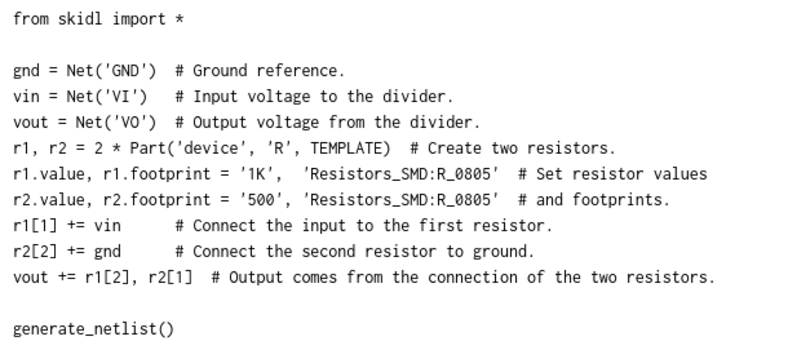
SKiDL is very, very cool. It’s a bit of Python code that outputs a circuit netlist for KiCAD.
Why is this cool? If you design a PCB in KiCAD, you go through three steps: draw the schematic, assign footprints to the symbolic parts, and then place them. The netlist ties all of these phases together: it’s a list of which parts are connected to which, the output of schematic capture and the input for layout. The ability to generate this programmatically should be useful.
For instance, you could write a filter circuit generator that would take the order, cutoff, and type of filter as inputs, and give you a spec’ed netlist as output. Bam! In your next design, when you need a different filter, you just change a couple of variables. Writing your circuits as code would make arranging the little sub-circuits modular and flexible, like functions in code.
At the very least, it’s an interesting alternative to the mouse, click, drag, click paradigm that currently dominates the schematic capture phase. Just as some of you like OpenSCAD for 3D modelling, some of you will like SKiDL for circuit design.
We’ve become so accustomed to the circuit diagram as the means of thinking about circuits that we’re not sure that we can ever give up the visual representation entirely. Maybe designing with SKiDL will be like sketching out block diagrams, where each block is a bit of Python code that generates a circuit module? Who knows? All we know is that it sounds potentially interesting, and that it’ll certainly be mind-expanding to give it a try.
Give it a shot and leave feedback down in the comments!


A while ago, I wrote an explanation about why I built SKiDL: http://www.xess.com/blog/are-you-in-an-abusive-relationship-with-your-schematic-editor/
The biggest benefit I see to KiCAD is usage of simple plain text files for all the design files, which can easily be adjusted outside of KiCAD, either manually or via scripts/programs like SKiDL.
I wonder if my submission got this entry posted.
I wrote something like this for work a few years ago, recently I’ve been toying with taking it to the next level:
https://gist.github.com/nmz787/10c60e76941a8e5de624454666ea65b3
https://gist.github.com/nmz787/ae4a6121ce4aa42c2caed5b062b97c70
A paper which those are based on:
http://dl.acm.org/citation.cfm?id=2967072
Wow, I had no idea Hackaday would try to render those URLs I posted! I didn’t expect or intend for it!
dude… awesome! you hacked the comment section!, now letd´s see if we can display the entire codebase for the linux kernel ;)
Endgadget and HaD both use WordPress. Maybe HaD can borrow their URL code which only shows part of a URLs content.
ROFL!!!
Brilliant.
Elliot, I see many interesting posts from you lately.
Dave, thanks for your dedication to the community over the years.
Regarding circuits, development techniques depend on requirements. Personally, I like the schematic to change automatically according to my doing in the PCB layout editor (back annotation). At the moment, Kicad doesn’t like this approach very much, but a scripting language could be very helpful for that. Drawing the schematic is in many cases a waste of time, if one person is doing both, schematic and layout.
Also, there other domains of electronic design where hardware is described programmatically, like the usage of VHDL and Verilog for logic. I’m surprised that we are so tightly coupled to the schematic capture stuff, which in most modern electronic design packages is also pretty badly implemented, unhandy and using pretty old user interface conventions. I’ve faith that developments like this can start changing things for good. I’m also always frustrated when I compare the high usability and the amount of innovation in the 3D CAD systems domain, with the “state of the art” Sch/PCB CAD systems, which are pretty boring. Thanks for this!
Programmatically if one wants to build up a functional library.
” I’m surprised that we are so tightly coupled to the schematic capture stuff, which in most modern electronic design packages is also pretty badly implemented, unhandy and using pretty old user interface conventions.”
My day job is mostly spent working with Altium, though I have worked with Orcad, Eagle, and Pads in the past. This is so painfully true. With SKIDL, I could describe most of my company’s products in only a couple of scripts and pump out variants in an automated process. I’m the only engineer in the company under 50, so it’s difficult introducing changes, and impossible introducing things that disrupt the existing workflow.
Awesome !!
It would be so nice if we could also do the board layout this way !!!
If you or anyone else is interested in checking it out maybe i could upload it somewhere like github.
Only part of my long comment uploaded. Basically, i have written a python script to generate a layout from a csv file.
Cool! I’m intrigued by the idea of programmatically generating a netlist and gaining benefits like source code rev control, ditching expensive CAD licenses, and easier design reuse. A few years ago, I ran across PHDL (https://sourceforge.net/p/phdl/wiki/Home/), but I have yet to use it for a real design.
Whenever I mention programmatically generating circuits, I encounter the objection, “How do you expect a technician to repair a PCB without a graphical schematic?” If you’re designing something more complex than some blinky lights or a single filter, it seems like a fair question. What is needed is a tool that can generate a reasonably-intelligible schematic based on a netlist input – not an easy task.
A graphical schematic is a just a view of the netlist though… so you can just program up a schematic generator (I did this a few years ago, actually, but for work). You can use heuristics to try and make the pages beautiful looking, or the real challenge is to apply 2D graph least-crossing layout algorithm… but this is one of those NP kind of problems. Maybe AI schematic page generation is the next thing?
Hmm, we don’t always need full schematics — if we’re generating schematics programmatically, we could say something like “what does this op-amp attach to?” and get the op-amp and all components it directly connects to drawn on the screen, but not the things the other components connect to. That’d be even better than a regular schematic most of the time, I think.
[Michai Ramakers] did something like this for his one-bit, one-instruction discrete CPU, described here: http://hackaday.com/2016/11/30/one-bit-one-instruction-discrete-cpu/.
I’m a big fan of human-readable project files. There have been many times in the past that I’ve had to fix directory names to move a project to a different machine (in video editing as well as in circuit design), and been relieved that the application developers had made this easy for me. But I’ve never generated the files from scratch – good job.
I don’t think I’m willing to give up my schematics yet. Comparing a schematic diagram with a netlist, I think it’s a whole lot easier to spot errors in pages of drawings than in pages of text. Having spent most of my life designing both hardware and software, the software (which has always been done in text) has been waaay harder to debug. Maybe we need more comprehensive ways of representing programs in a graphical way. I mean, something better than flowcharts and state diagrams. Though I HAVE found state diagrams to be very useful.
I am just started learning python out of curiosity but I did not know it is that much capable :)
Thanks for this great article :)
I would like to see HAD only run articles this useful.
I’d like a category system so we can filter the articles down to what we’re actually interested in.
– Hardware Hacks
– Software Hacks
– Inventions
– Art
– News
– Product Reviews
The existing tag system could be used for this!
I think this is very cool and practical. The amount of effort that goes into creating anachronistic symbols and then connecting endless pins like a monkey is disheartening. In analog world perhaps it’s still a very nice representation. For circuits that are mostly digital it’s a completely unnecessary step that only adds obfuscation.
It is slightly weird that it’s using Python as HDL though. It would be less of reinventing a bicycle if it used a standard HDL, a subset of Verilog for example. Perhaps extend existing functionality of Icarus Verilog?
Weird is a good word for it, but unless you’re trying to simulate the circuit, an HDL doesn’t really add anything. The advantage of using Python is that it is ubiquitous and free. Also keep in mind that the objective here was to produce netlists that could be imported into PCB layout tools, which HDLs don’t generally do since they are focused on IC design.
I do not think that Verilog is limited to IC design. It’s a common misconception that Verilog is a FPGA programming language, but its much broader than that.
Regardless, I think it would add a few things:
1) familiarity — potential users are more likely to know Verilog of VHDL already rather than Python + custom framework
2) a reverse of (1) — if you do not know Verilog and VHDL already, you would learn it and it will without any doubt come in handy later
3) Icarus Verilog already does a lot of work (most of it?) — at least in theory it should be easier to maintain one product instead of two. Provided that integration with IV or processing its netlists is a feasible task of course, I do not know.
4) it would be, in its own geeky way, incredibly cool to be able to synthesize from the same source a transistor circuit, a 74xx-based circuit and a FPGA bitstream
The (4) is probably the least practical but from my perspective is the coolest.
boldport uses Inkscape to display this kind of info in visual form.
Inkscape has python extensions.
It’d be great to jam this further into boldport’s integration. Maybe go to and from KiCAD in this way ??
Why can’t I use the prompt to report a mistake? Is it wrong?
Want to make mobile bitmap