It’s OK, you can admit it — from the time you first saw those huge electromagnetic cranes in scrap yards you’ve wanted to have one. While it may not fling around a car, parts donated from scrapped microwaves can let you build your own electromagnetic lifting device and make that dream finally come true.
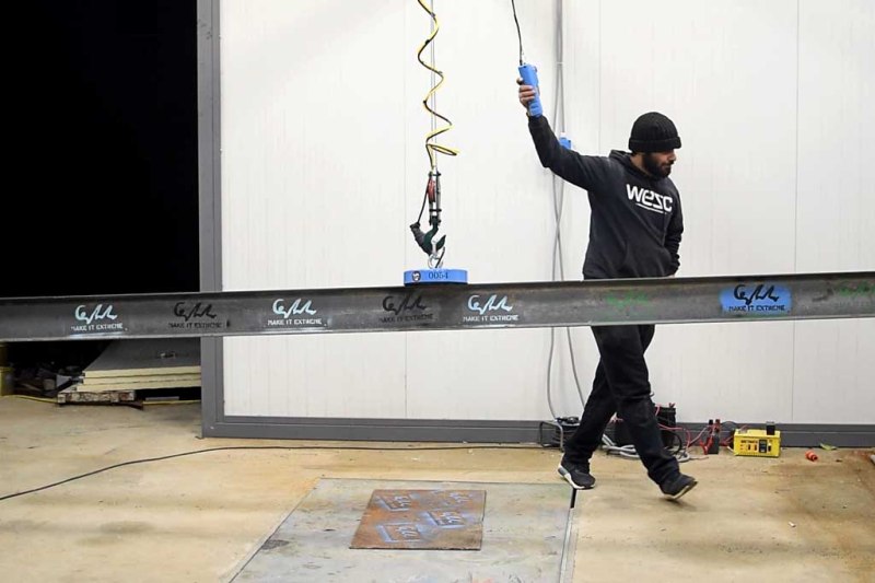
We recently watched [MakeItExtreme] turn a couple of microwave oven transformers into a somewhat ill-advised wall-climbing rig. It looks like that may have been the inspiration for this build, and the finished product appears to be a tad more useful this time. The frames of three MOTs are cut open to remove the secondary coils and leave the cores exposed as poles for the future magnets. A shallow dish is fabricated out of steel and the magnets are welded in place.
With the primaries wired together, the magnets are epoxy potted, the business end is faced off cleanly, and the whole thing put to the test. [MakeItExtreme] doesn’t go into control details in the video below, but the website mentions the magnet being powered off a 24V 15A power supply with battery backup in case of mains failure.
They’ve lifted 200kg so far, and it looks like a pretty cool addition to a shop already packed with other builds, like their MOT spot welder and a propane tank sandblaster.


nice work,
I recall a battery add from the 70’s or 80’s that displayed the power of a couple of 1.5V cells powering an electromagnet that could lift a car.
I bet the copper coil weighed as much as the car.
It’s not easy to get that many amp-turns out of such a feeble source. You can wind arbitrarily many turns in a coil and create ridiculous magnetic fields, but the series resistance grows to the point that adding more turns decreases the current and diminishes the field.
If I remember right Edmund sold a one ton lift magnet that would work with one dry cell. It was about 3 to 4 inches in diameter and half as thick with a single piece of iron with a circular groove for the coil. I saw a similar magnet lift a car at the Museum of Science and Industry in Chicago decades ago. The trick is perfect flat coupling to a thick flat piece on the load.
https://www.aliexpress.com/wholesale?SearchText=magnetic+lifter
200kg at the flip of a handle. No electricity involved.
(The 2000kg version has a bigger handle :).
The real magic would be in getting Alexpress to actually deliver.
No I don’t want one, because I have a computer museum and I don’t feel the need to instant-wipe all my floppy disks at the flip of a switch.
Colin Furze has made magnetic shoes using same transformers two years ago:
https://www.youtube.com/watch?v=OqLi6lrOCzs
Colin makes a better video.
Meh – personal preference. Don’t much care for his whole on-camera persona myself.
Isn’t welding the core kind of a bad idea as it will short the laminated plates and make it heat a lot?
Does matter since he runs it on DC, even so the lamination are already welded at the factory, its how the transformer is assembled.
I love the concept and the build. But does potting with epoxy resin have enough strength to hold magnets in place? I did not see any mechanical fastners holding magnets in place . If epoxy cracks I see magnets pulling out of metal bracket and failure .Over to someone with engineering experience please.
He welded the base of the magnets to the plate that is hold directly to the crane with a hook. Look again.
I’ll try and keep this short and simple.
The MOT cores are welded to the head, so they’re not coming loose without shearing. The sole purpose of the epoxy would be to keep the coils mounted to the cores (as well as keeping them free of damaging debris that would short the coils.) The only force the epoxy sees is from the eddy currents trying to push the coils away from the core (or vice-versa.) That energy then becomes the electromagnetic force that gets “transferred” to the ferrous cores – that are welded to the head. Since the force from the eddy current is fairly weak, there’s an low extremely low risk for such a failure. Not impossible, but it would take a catastrophic failure.
Im wrong they welded them. Forget my last comment.
Forget what?
that’s the spirit.
That’s not OSHA approved footwear for this kinda thing. Bye Bye Toesies.
OSHA, what that hell is that……
An organization that declares everything unsafe yet doesn’t have to actually DO anything.
Dude routinely welds wearing shorts and flip flops. He’s also known to weld quite a bit of galvanized steel, as he does in this video with the lifting ring. Not saying he should do any of this, but there it is.
Anyone know a good source of information for dummies on electromagnet math? I’d love to build one of those electro magnetic pan brakes, but blindly connecting 240VAC to a coil scares me.
http://ludens.cl/Electron/Magnet.html
They do not connect 240VAC , they connect 24v DC with a 15A source. Remeber AC is a sine signal, you don’t want a signal that turn off 60 or 50 times per second.
There are lots of AC coils out there – in my parts bins I have AC driven relays, and AC solenoid valves. How do they work?
One possibility (on contactors) is to have a split pole with a copper ring one one half. This is similar to a shaded pole motor. The current which is induced in the copper ring (shorted winding) is out of phase with the current in the main winding and smooths out the zero crossings. Another possibility, mostly used on valves, is to rely on the inertia of the core, here the dampening effect of the fluid also helps. The device is just not fast enough to follow the 100Hz (or 120Hz in some oversea countries) ripple.
So if I am looking to make the magnet more powerful, other than supplying more current, could I wire the primary and secondary coils of the microwave transformer together in series to get more turns (being mindful to keep the direction the current flows the same in both coils)? My thoughts are that it would increase the resistance a bit from the added wire but that the magnet would have a lot more turns. Am I missing something or am I onto something? Thanks in advance!
It would work, you could try just one winding on its own to start with but beware the voltage surge you get when disconnecting the current, as a minimum it should make a nice spark, even with a small battery driving it, at its worst it is shocking(!) I think the reason for winding your own coils is to get the optimum ampere turns for a chosen voltage, if you use what the transformer comes with you will have to work out what voltage gets you the highest magnetic strength without burning out the winding.
If you know the Wattage of the transformer and the input voltage of the oven then you can calculate the approximate current the primary (thicker wire) can carry. Example: 500W 220V gives 500 / 220 = 2.273 Amps. This is the current the coil is designed to carry, and this current should normally take the core close to saturation without generating too much heat. The coil resistance can be measured and an appropriate DC voltage applied. I suggest a current of around 1.5 times as long as the power is not ON permanently. Regarding the use of both coils, the secondary coil is much finer wire and will require a proportionately higher voltage. Assuming the output voltage to be 2500, then the current required will be 500 / 2500 or 0.2 A. The secondary coil has worse properties for dissipating heat, so I would only allow a 25% over current, but just try it and if it gets too hot to hold, reduce the voltage. Allow 20 minutes for the coil to cool between tests. Putting the coils in series, or in parallel does not make sense because they have such different characteristics: better to find two ovens with the same transformer and use both primary coils or both secondary coils, which can then be connected in series to raise the working voltage or in parallel to keep the voltage down but double the current. As someone has already said above, disconnecting the coil produces a spark, that in the secondary coil will be a very high voltage – use a totally enclosed switch rated at at least 250V 10 A, with a 100 Ohm resistor in series with a 0.1 microfarad capacitor across the coil to reduce the sparking and increase switch contact life.
Jake, in parallel you get the same coil count. Key word/s… ampere-turns. That says it all.
Next is the flux density that the core will accept to help keep the flux created, focussed.
And if your primary and secondary are of different wire gauges, the thinner one becomes your limiting current factor. Wired in parallel gives the same ampere-turn count, but with less resistance, possible more AMPeres, so more aoere-turns.
But used separately, you might drive 10A through a primary and perhaps 15 through a secondary (almost requiring 2 differsnt sources,) dependant on wire gauge as the limiting factor. Now with 2 switches, you can drive the magnet at A, B or A+B strengths!
If you wrap your own coil, consider wrapping a thermistor or thermocouple into the windings. Insides may heat up before outsides. Expoxies have limits. You don’t want failure halfway up 50 stories, whether mangni-shoes or a load of pig iron.
I’m wondering why nobody is simply rectifying a 120vac input for dc wiring the secondary coil? It means you don’t have to swap the coil location or use a dc power supply.
I have a trans with a secondary resistance of 82ohms. Putting 120vdc through it would be about 175watts (assuming I do a good job of determining wire size and 1.46amps is ok)
24v 12a is not that much more at 288watts. I’m sure I’m missing something to do with electromagnetism which makes the secondary unnatractive?
2 reasons. 1, a really long extension cord causws power losses so it has to be a BIG conductor, weight. 2, the rectifier can fail under EMP, and you’d fall, failing in whatever mission you were on, which would be the only reason to be walking up a 50 story bldg using these shoes. Just use a car battery, (LI) up the weight-carrying ability of your device, and fast get to the top beforeyourunoutta’juice!
I’m wondering why nobody is simply rectifying a 120vac input for dc wiring the secondary coil? It means you don’t have to swap the coil location or use a dc power supply.
I have a trans with a secondary resistance of 82ohms. Putting 120vdc through it would be about 175watts (assuming I do a good job of determining wire size and 1.46amps is ok)
24v 12a is not that much more at 288watts. I’m sure I’m missing something to do with electromagnetism which makes the secondary unnatractive?
You are probably using 82 ohms, resistive… that’s with DC. With AC, you need to know the ohmmage stated as reactance. It’s Z, not R.
I used a bridge rectifier from a stick welder, it takes 120vac down to 63vdc with no load. Out put it into a pair of MWT primary coils in parallel. Just like this one. Works but draws too much current. The field strength is around 300 pounds. The coil resistance is about 3 ohms, and draws around 20 amps.
I am going to try a rheostat on the input voltage to see if I can drop the rectifier output voltage to around 30v. Right now it works but will pop a15A wall circuit breaker after 15-20 seconds. But it is a super strong magnet. Limiting the current is the key I believe. More later
Pull half of the bridge rectifier. That cuts power in half… mainly halving the current.
How much volts or power it needs for per microwave magnetic lifiter as they use 3 in the video ..how much each requires electricity.
Did I miss something? Probably! Are the 3 magnets wired in Series or Parallel for your 24 volts @ 10 amps? Will the placement on the plate affect the interaction between the magnets or will the winding cores take care of that?
Ive hooked up a transformer to a 12v 28w battery and get a very low powered magnet. how do i increase the power substantially?
How did you wire the battery back up so it’s not getting over charged by the power supply but still in the circuit so even if power is cut it still has a uninterrupted power source?