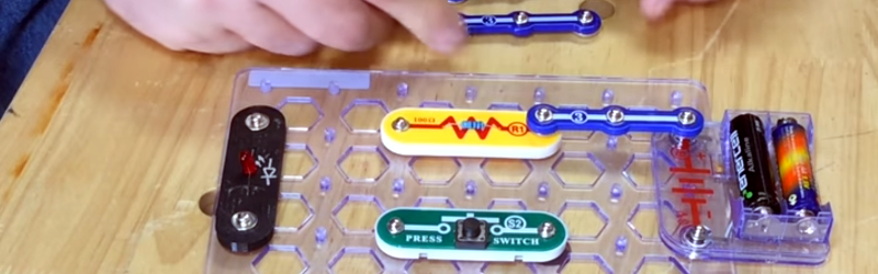
For just about as long as there have been electronics, there’s been a search for a way to let students and hobbyists build projects without a lot of effort. A board with Fahnestock clips was probably the first attempt. Today, it is more often the ubiquitous solderless breadboard. In between, we’ve seen copper pipe pieces and rubber bands, components mounted on magnets that hold them and make connections, and other even less probable schemes. A few years back, a new method appeared: Snap Circuits. The name almost says it all. A baseboard has mounting holes for different components. All the components make their electrical connections and mechanical connections through a common snap like you might find on clothing. Even the wires are little segments with snaps at both ends.
One problem with any system like this is how to integrate custom components. Of course, with the snaps, that’s not very hard, but [Chuck Hellebuyck] got creative with TinkerCad and worked out how to 3D print custom modules for the system. You can see his video, below.
The system uses 12mm snaps, and although [Chuck] doesn’t do it, you could probably 3D print your own baseboard, too, and not use any original Snap Circuit equipment if you wanted to do so. He did have to doctor the snaps to be double-sided using a grinding wheel, but otherwise it was fairly straightforward. He marked the component markings with a Sharpie, but we might have embossed or engraved the symbols and designator right into the plastic.
You might not be interested in using Snap Circuits, but it does make a nice practical example of using TinkerCad to build a part that mates with something that already exists. You can find the end result files on Thingiverse.
If you prefer a more normal connector with multiple wires, check out Pure. Or, if you are 3D printing, you could get some conductive paint and just do the whole board.


https://www.circuitscribe.com/ is kind of similar?
Exactly what the system needs; currently almost everything interesting in the kit is a black blob. An ATTiny would be perfect for this, not to mention blinkenlights.
I’ve also found the lack of power rails limits the utility of the system. I’ve considered an offset rail next to the current standoffs, with a rectification bridge to make the connection polarity agnostic.
He does a good job of demonstrating the cad tool which is something I’ve been missing.
Grinding a gazillion little snaps by hand, NO THANKS! I see no point in doing this at all, or in using a snap system. Better to teach using http://www.falstad.com/circuit/ or https://sourceforge.net/projects/simulide, then move on to the real thing as soon as students show that they have sufficient understanding of what they are doing.
I love the Falstad simulator for teaching, and occasionally use it for trying out various ideas before building a prototype.
Science fair springy things were the best. I started with one when I was about 6. Still have it 34 years later. Thanks mum for getting me hooked on electronics! :-)
Agreed. While I applaud all the efforts going into these sorts of teaching tools (and I’ve seen a lot of them ), they each end up with two distinct issues:
1: fundamental limitations inherent in the design. Manufacturing limits, costs of materials, limited parts set, limited power rails (as mentioned by Aussie Lauren).
2: more important to me, while I like abstraction in general (high level languages are a godsend), too much abstraction in hardware I feel actually limits real knowledge of the subject and troubleshooting skill development. The maze or puzzle like effect of building circuits with wires, raw parts and a breadboard offers so much more learning potential than simply copying the orientation of building blocks from a photograph.
Hacking your own parts to expand the set is really awesome.
But Ii got so much more out of the springy science fair kits. Troubleshooting faulty wiring, identifying and replacing broken wires, adding my own bits onto the side.. I remember my first use of breadboard was as a mix of breadboard circuit and springy circuits.
And making new parts is just holes in card stock with springs and the component.
Well this sounds like an upgraded version of those “springy” kits. Even the idea of a “bus” should be pretty easy.
I disagree with this BREADBOARD IS FINE
Can buy 6 pack of Breadboards for $5 +$5 for assorted Transistors resistors and LEDS and 20cents for a set bat clips, Add some cardboard and Pen, poke holes in cardboard fit to breadboard OMG CHEAP TEACHING TOOL.
FFS with these over the top Ideas why not use what exists this is just creating waste.
Dude. This is for kids. I have one for my 6 year old daughter, and it’s awesome. Settle down.
What was wrong with copper wire and nails in a board
I used to use this. Quite fun and very readily available where I grew up (China). These kits were in practically every toy store. In fact they were almost as ubiquitous as Lego (and it’s Chinese clones). It’s nice to see the ability to stick stuff in. Would have loved to add a couple of opamps/relays in the kit.
This system needs bases for 100-pin BGA and QFP packages.
Snap Circuits (Elenco) are ok. 750 kit comes with a blank to”add your own” two pole and alligator clips. The good thing included was an ‘oscilloscope’ that’s really just a cable with resistor for pc sound card. Cheap scope with software. Not enough warnings as to where NOT to use other than !use only with kit!. A cheap DMM would be nice. Much more than a couple of new components and an experienced would push to a solderless breadboard and direct/wean newbie away from those kits.
I got it for my niece. She started with a 100 kit and zipped thru it only with vague idea what was really going on. Parents marginally clueless.
My finding is that those tend to be more puzzle/model building than circuit design. Where the end result is something not always “cool” or usable in the kid’s mind. So time wasted and negativity built. Black boxed modules not helping. Failure of snaps not always connecting sucked due to layered build- adding to frustration. Snaps may be too stressfull for little fingers in repetition. Spatial skills increase due to layer/grid layout planning. More to mechanical there.
I agree that Expanding these kits is to some point negative and unnecessarily expensive in time and money. So -not seeing it IMO.
I know some schools use these up to college level but only to 101 intro with much more explanation and a cheap mutimeter. Then solderless breadboard trainers come into play. Also made by Elenco. ha.
FWIW she liked ‘old school’ 150 in 1 springy goodness more. Also made by ‘ that’ company and imported by a Shack that fell apart in a time far far faaar away.
I have read your blog it’s really good
Grabbed a SC-100 kit from the Goodwill for $1 on the Seniors 50% off day. Thinking will be good for the 6 year olds. Here are some 3D prints I figured I’d share here since was looking for: https://www.yeggi.com/q/snap+circuits/