A tool breaking in the midst of a CNC machining operation is always a disaster. Not only do you have a broken tool (no small expense), but if the program continues to run there is a good chance it’ll end up ruining your part too. In particularly bad cases, it’s even possible to for this to damage the machine itself. However, if the breakage is detected soon enough, the program can be stopped in time to salvage the part and avoid damage to your machine.
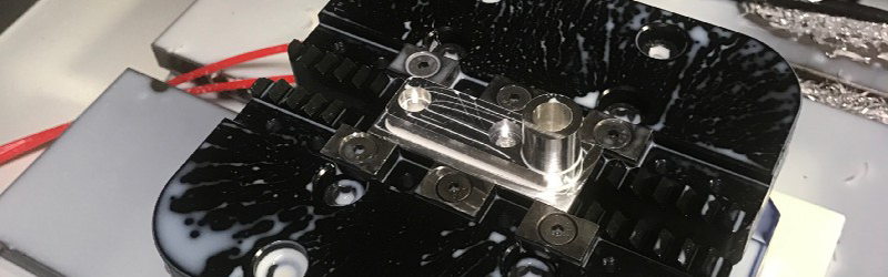
Many new machining centers have the ability to automatically detect tool breaks, but this is a feature missing from older machines (and inexpensive modern machines). To address this issue, [Wiley Davis] came up with a process for adding broken tool detection to an older Haas mill. The physical modifications are relatively minor: he simply added a limit switch wired to the existing (but unused) M-Function port on the Haas control board. This port is used to expand the functionality of the machine, but [Wiley] didn’t need it anyway.
With the limit switch wired, [Wiley] then wrote a short subprogram to move the tool to the switch. When this subprogram is inserted into a part program, the machine will attempt to touch the tool to the switch. If contact is made, the program continues. If contact isn’t made, it just waits until the operator comes by to check things out. In most cases, this will mean the tool is broken, and the operator can proceed accordingly. Otherwise, the program can be continued from there.
While the instructions [Wiley] has posted are meant specifically for a Haas mill, a similar approach should work for most CNC mills. You’ll need an unused port for the limit switch (that you can access), but that isn’t uncommon. The g-code for the subprogram is generic and should work for most any mill. If you’ve just purchased your first CNC mill, this is a great way to avoid wasting material as you go about learning the basics of CNC machining.


This is only somewhat related, but I’ve been intending to modify the closed-loop spindle controller on my mill with something that looks at the current draw or proportional term of the feedback loop and if it sees that rising rapidly triggers an about-to-stall alert back to the controller to make it slow down the feedrate. Has anyone else played with something like this? I was reminded of it because the opposite condition: suddenly seeing the spindle current draw drop to nearly zero, would be an indication that the tool just snapped off and the spindle’s running empty, and that might also be a useful thing to feed back for operator intervention.
You would need some safe guards in drilling programs where the load goes from high to zero very quickly. Same applies to mill vertical retracts. Mabe it could ignore rapid retracts and maybe give -Z move a second to stablize current.G0 moves with a sudden zero to high should trigger the alarm, as you probably just ran into something :-(
Such is life in being a guide dog for a “BLIND GIANT”.
Load does go to 0 when you retract from piece. When you run into the stock and motor load is still zero means something goes wrong.
But touching tool before tool change is probably simpler and as effective.
Look up Through-Hole Bolt Load Cells. Place one or more strategically to sense the load placed on your spindle/bit. You can adjust the feed rate to attain the desired cutting pressure. You can also place different load restriction for each bit.
Yes, I built that functionality into a planer mill. It had 3 hp servos and a 10hp spindle motor turning cutters thru a 3-speed planetary transmission, and controlled by a Toshiba vector drive.
One of the common jobs was drilling 3″ holes in boiler plate. Lots of them. The trick was to feed the drill as fast as electricity could do it, but not stall the spindle [and chip the drill].
I configured the VFD to provide an output when spindle current was over some high percentage of maximum, and used that to invoke Feed Hold until spindle current dropped.
It worked like a hot darn! There was no way to manually tweak the feed rate by hand and get it to work as fast or as well as the electronics could do it. I hooked this up to a switch so I could invoke it at will on anything that took big spindle power. Made us nothing but money on drilling tube sheets.
If you have a controller that spits their current Gcode out you could detect if the current command is G0(as free movement) or something else(G01-G03) – milling straight, left, right
While an explicit “Is my tool still as long as I expect?” test helps, it doesn’t account for the tool breaking mid-pass. And running back to the test switch before each pass might be unacceptably slow.
Thinking about my pcb mill and how it probes the board to manage “levelness”, could a voltage be applied between the spindle and work clamps and using something like a missed-event / late-shout pattern to detect an unacceptable delay between “touches” to detect a broken tool?
The idea here isn’t to save the part or the time wasted air-milling the part with a stub, it’s to save the next tool (and all consecutive tools) that have operations where the first tool was supposed to remove material, like for instance a feature (a hole, or pocket etc..) on the bottom of a pocket that it expects to exist, but actually doesn’t because the tool broke.
You’d also need to have continuity between the bit and the reference, which wouldn’t necessarily be the case if you’re milling-out something that’s already been isolated from the rest of the workpiece. This is most notably a problem for something like a PCB, where much of the work area may not have continuity to your reference point, because the substrate isn’t conductive. However, for a homogenous piece of (conductive) material, this seems like it might work.
would only work for parts made of metal and you would need to have the work isolated from the rest of the machine
I’m not so sure of the need for isolation.
If the sense current was DC, certainly, but what if you used RF? Could you “load up” the big metal loop formed by the tool and the machine, and then look for its impedance to change?
Come to think of it, in most tools the cutter is touching and leaving and touching the workpiece rapidly, which might make a nice FM signal if you excited it with a simple carrier. Look for the modulation to go away and it means you’re not milling anymore!
A much bigger problem, IMHO, is the fact that most passes start and end with a moment of air-milling, so you’d have lots of time when the tool isn’t making contact *and that’s perfectly okay*. The trick becomes programming it to know when it should be expecting conductivity and only alarm if it’s missing during those times.
In the general case, you may not be able to know when you’d expect to see continuity (or load changes — whatever you’re monitoring). It seems like material removal can happen during periods of +Z, -Z and well as no-Z movement. Without knowing which path segments are expected to be removing material, you can’t know when you should expect contact. You may be able to make some assumptions based on a priori knowledge of how your G-code generator works to help you intuit this condition though, but that’s a pretty fragile solution.
I’m not sure that this is a problem that one can generally solve without some type of meta hints that get dropped into the G-code by the generator. You’d have to simulate the job to identify when the bit is in contact with the work without this.
How about using an acoustic mic rather than continuity? That might help with the non-conductive workpiece problem. In general I’m more a fan of monitoring the current draw of the spindle, but even that gets iffy if you’re milling something like foam, which may not even generate a measurable load. You probably won’t be breaking bits in such a light-load material, but it could still get broken another way.
As long as you can get line of sight to the the tool tip, an image sensor may be the way to go. You wouldn’t need to home to touch a switch. Having the camera at a position fixed up near the spindle would probably give you line of sight almost 100% of the time. Keeping the lens clear is probably the biggest challenge there.
I wonder if a simple piezo on the workpiece could work, the RPM x number of flanges on the tool should be the frequency… I could imagine it might even detect mismatches in feeds and speeds, as I would assume the sound to be different…
or instead of a piezo, perhaps the vibrations could modulate the reflection of a laser (mounted on the milling “head” holding the spindle, forgive my lack of terminology) dot of light on the workpieze but a bit away from the milling bit, modulated at f Mhz, so that the reflection contains f+-x Mhz signal, where x is the frequency of mechanical vibrations… the advantage could be that the laser dot is always near the bit, while a piezo would have a specific location on the workpiece throughout the process…
can those of you who regularly mill chime in if you can hear when the cutting is (in)appropriate? how much effort would it be to make audio recordings of different kinds of wrong cutting and correct cutting in different materials? if we have enough recordings perhaps people without mills but with digital signal processing skills could try to characterize the difference in sounds?
You can hear inappropriate cutting for sure, it is a method used by a lot of manual machinists to “feel” for the cut they are making. For CNC work though, cutting sound is a poor way to optimize your machining operation, merely a way to tell if you are way off base.
Why couldn’t you solve this with a camera watching the bit. Have it periodically take a picture, apply some transforms of some sort (edge detection maybe?) to accentuate the bit, and then compare it to the previous picture(s). If one picture doesn’t look right, do an explicit Safe-Z move, and then take another one to try and confirm the problem and stop, or everything is fine, and continue on.
You could I suppose. It’s just wildly more complicated than a switch. Don’t forget the environment either, chips on the tool could invalidate the image and coolant on the camera could obscure any image at all. On top of that, now you need a separate device to do the image processing, keep a library, you don’t have any (convenient) way of keeping track of which tool the machine is using or when it switches tools.
I think the switch is a better fit for “Why couldn’t you just…”
I used to be a professional CNC mill operator… in a professional setting, a mill isn’t left unattended. An operator “doesn’t come by” to check on the machine, he watches it during the entire operation. He might be deburring parts, might even be doing a crossword… but he’s within arm’s reach of the big, red e-stop button, and he’s listening to what the machine is doing. He watches when it changes tools, he hears when a cutter breaks.
This is a neat hack, but nothing substitutes for a human operator supervising the tool.
Well said, I own a few machines more than capable of doing as they’re told without human interaction, but I don’t let them, not even the automatic electric hacksaw, even if I’m just mopping up coolant as it runs out the end of a tube.
I ran a mill for two days. The job required me to clean up the part with an angle grinder which took just as long as is took the mill to make the part. I broke five tools in one run because I couldn’t hear when the tapered part of the endmill (the part you aren’t supposed to cut with, but the program did anyway) clogged with chips, and melted it’s way through the rest of the cut and made a massive burr. Then the other tools came set to evade to 0.02″ above the surface, and snapped off near the burr they passed right over. The stupid part was that this was just drilling holes (and tapping a few) in a laser cut plate for a trailer. Half of the operations in that machining cycle should have been done on the laser cutter.
I am a much happier laser operator now in a much happier shop.
I would say nothing is a pretty strong word. It’s common place for shops to run lights off on weekends now with newer machines, even 9 axis mill turn machines big. Between tool life-time substitutions, and breakage checks, its advanced enough to offset the cost / risk of a major crash event. Even then, axis load sensing tends to stop any really bad damage.
If you’re doing one-off prototypes and always running new programs, I would generally agree with attending the machine. If you’re making production parts from programs that are well vetted, there is no reason to be overly paranoid and attend the machine the whole time. Particularly if you are checking that your tool did not break between auto-tool changes. There are exceptions of course, it comes down to cost and risk – what is the employee’s time worth? What will the cost be if something goes wrong and what is the likelihood of something going wrong? I feel like in may cases the employee’s time would be worth more than the expected cost of a milling accident.
I can tell you, from also being the same, that leaving the machine is extremely common in shops I’ve worked in. Usually we’d have multiple machines running, and we’d rotate between checking them. Seems awfully inefficient to have an operator standing there just watching a CNC mill do its thing for hours.
Many operators now run machines what we call “lights out” ie at night when everyone has gone home. Tool breakage detection is certainly a big thing.
I completely agree. “If you’ve just purchased your first CNC mill” you really, really, shouldn’t be leaving it unattended. I don’t think my finger left the e-stop the first few times I tried milling.
The switch, if properly positioned, could also be used to measure the length of the tool, perhaps more accurately than using manual jogs and feeler stock.
I have found typical limit switches are not accurate enough for machine positioning. A typical homing switch used to find machine extents is (in my experience on a tormach and a shapeoko) only accurate to +-0.02-0.03″ or so. Not accurate enough to use for measuring length of a tool. This is based on situations where you find part zero, cut some of your part and then hit e-stop or turn the machine off. You can’t just turn the machine on, run a homing routine and press cycle start, you typically have to find your zero again because the limit switches don’t trigger very repeatably.
All “industrial sized” CNC machines I know of, don’t use the limit switches alone to find their home position. They use the limit switch to know when to slow down and start watching for the next marker pulse on the encoder that spins with the ballscrew.
That makes sense, I have never had a machine that successfully uses this feature.
What if the limit switch happens to trigger near the marker pulse though? I could see it trigger after a marker pulse during one homing instance and right before a marker pulse the next time you home – giving an error equal to a full turn of the ballscrew from one homing to the next. That would be significant error I bet.
That means the machine builder screwed up. When building a machine that homes to index, they make sure the mechanical switch trips about a half-turn away from the index pulse, so that a minor variation in the mechanical switch doesn’t cause exactly the problem you describe.
I would agree that mechanical switches may not be very repeatable, but I would differ in regards to inductive or even optical switches.
I outfitted my CNC router with inductive homing sensors and it’s repeatable within .0005 (verified by running around 100 homing cycles followed by a G0.)
The connex500 at work homes the Z using opto-interrupters and will resume a job to within one layer height. (.0005 in high quality mode. )
I found that the specific homing routine is the key to repeatable results.
Good to know. I should get some inductive switches for my shapeoko, it has been a great low cost machine but homing is not repeatable enough with the little mechanical switches.
If you’ve just purchased your first CNC mill
then you have no business leaving it run unattended.
Amen Brother!
I don’t leave mine running unattended even after 2 years of ownership UNTIL I have run a part successfully one time and am reasonably sure that the speeds and depths are within the ability of the machine to handle without breakage.
I also utilize a webcam to keep an eye on it while I’m in another part of the house doing things. Just need to add emergency stop capability to it from the phone or tablet.
What if you record the load of the axis and/or head as the first part is created. You would then have a profile to compair against as the subsequent parts are manufactured?
There are MANY types of CNC shops. Some run one off prototypes and others run days of un-attended machining. So skipping how and why to use a tool sensor…
Commercially they use something similar to set tool length, but also to verify the tool has not broken. A simple but probably more accurate switch like this would have a flat faced piston above the switch for the tool to contact instead of the switch directly, giving a larger target. The design should also plan for an easily replaceable break point or some other fail safe if the switch fails (or human error)
What if we put a camera into machine, that will track the tool in the realtime video (with some help of AI) and send signal when a tool brake is detected? We’re actually a startup working on that kind of solution, would be great to hear your feedback!