Reaching the end of a spool of filament when 3D printing is inevitable. The result ranges from minor annoyance to ruined print. Recently, I needed to print a number of large jobs that used just over half a spool of plastic each. Unwilling to start every print with a fresh spool (and shelve a 60% used one afterward), I had a problem to solve. What my 3D printer needed was filament monitor, or at least that’s what I thought.
After reviewing some projects and aftermarket options, I ended up making my own. Like most prototypes, it wasn’t an instant success, but that’s fine. One of the goals of prototyping is not only to validate that the problems you’re solving are the same ones you think exist, but also to force other problems and issues you may not have considered to the surface. Failure is only a waste if nothing is learned, and the faster and cheaper that learning happens, the better.
Sensible design steps also help minimize waste, so I started by looking at what kind of solutions already existed.
My Assumed Need: A Filament Monitor
The filament monitors I found were aftermarket or DIY devices. Not counting incomplete Kickstarter projects, I found the aftermarket Tunell Monitor design by [Aaron Tunell] as well as some DIY projects. Most monitored the movement of filament by turning an encoder wheel in some way (filament feed encoder by [Florian], and filament monitor by [RodLaird] for example) and one used the guts of an old PS/2 mouse as a sensor.
These projects were clever, but my needs were much narrower than the solutions they offered. My problem was not a lack of filament encoding. My problem was that over the many hours that made up a print, I couldn’t be there for the right four minutes.
Actual Need: The Right Four Minutes
On my printer, if a spool runs dry I can salvage the print as long as I have time to load a new spool and feed the new filament right up against the end of the old filament as it enters the extruder. I measured a minimum four-minute window to do this. Four minutes is plenty of time, as long as I’m ready and able to do the swap when it happens.
The missing piece wasn’t really that my machine didn’t know when the filament spool was empty. The problem was that I – the operator – had four minutes to act when it did empty, but I didn’t have a good way to know when that was.
By narrowing the scope of the problem in this way, I could keep the solution simple. If I assumed I would be within earshot of the printer at least during the hour or two that the spool is expected to run out, I should be able to solve my problem with a simple audio alarm. When the last bit of filament comes off the spool, sound an alarm and I’ll have at least four minutes to feed a new one.
I decided to make a prototype of a simple filament alarm that did nothing more than that. I called it Mister Screamer.
Design Overview
Mister Screamer’s job can be summed up as:
- When filament is present, nothing happens.
- When filament runs out, scream your fool head off.
The key elements are:
- 3D printed enclosure
- Self-contained (no external power or signals)
- Small enough to be clamped directly onto the filament itself; does not need to be affixed to the frame of the printer.
- Electrically simple: coin cells, a roller switch to sense filament, and a buzzer.
- Easy to turn off when responding to the alarm.
Prototype
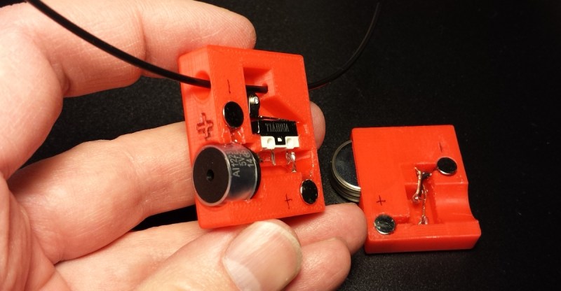
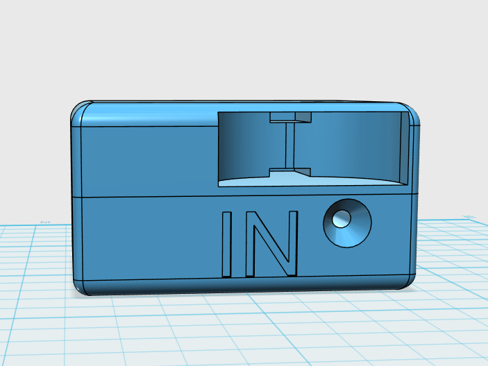
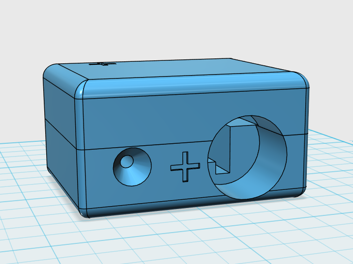
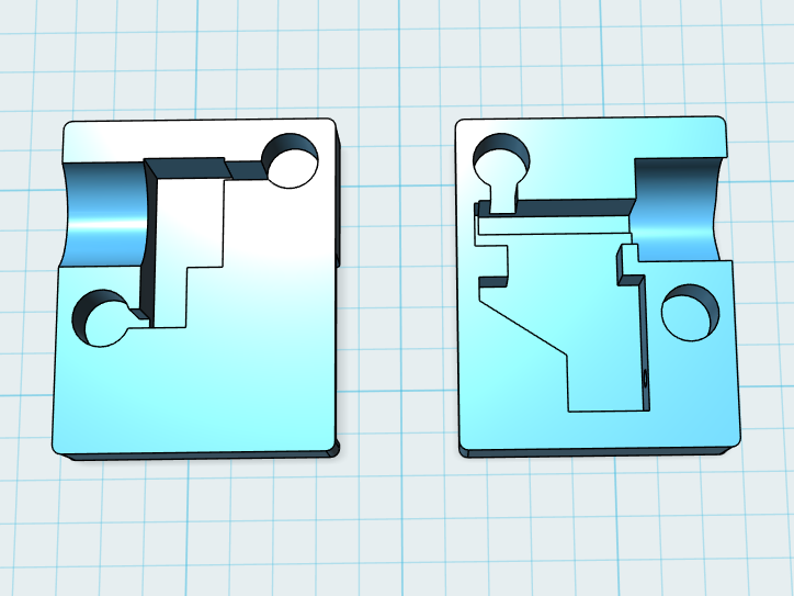
An enclosure was designed as a sort of clamshell to hold the components. Magnets hold the shell together and also act as power connectors, so putting the halves together (or pulling them apart) serves as the main power switch. Two CR2032 coin cells power a small 80+ decibel buzzer, controlled by a roller switch. When the device is not shrieking, it consumes no power.
Filament is fed through a hole that lets a normally-closed roller switch sense whether filament is present or not. When the roller is pressed down, the circuit is open. When the filament is gone, the roller is up and the circuit is closed; the unit begins howling at about 80 decibels until the halves are pulled apart (or filament is re-inserted).
Assembly
The two halves were printed in PLA and components glued in. With the exception of soldering wire leads to the magnets before installing, connections were soldered point-to-point after the components were secured.
Warning: LOUD beep at about 1:30
[wpvideo USFve0zv]
Trial Run
 The first trial run of Mister Screamer was a success. The alarm activated, I was able to hear it and easily disable it before feeding a new roll with time to spare. However, while the concept was validated, two big problems became clear:
- There was far more binding and friction put on the filament than I expected. The extruder was able to manage, but I was never very comfortable with how hard it seemed to have to work to pull the filament through the alarm unit. When pulling the filament by hand it seemed fine, but once installed and “free-floating”, the effort needed to pull the filament through increased dramatically. Often the prototype simply rode the filament until it could go no father, and was physically butted up against the opening of the filament guide tube. This increased friction.
- When the filament ran out, the prototype fell some distance to the tabletop. The impact nearly popped the batteries out, as they were only a friction fit. It could also have popped the shells apart, killing the power. Luckily neither happened, but it was clear it was a risk.
Lessons Learned
Prototypes don’t just test design ideas – they help to discover problems or issues that haven’t been considered or anticipated. Also, sometimes things go better than expected or work out especially well.
- A soldering iron with an old tip comes in handy for making rough alterations to a PLA enclosure; either use it like a hot knife to cut or melt plastic away, or to heat metal components and melt them into the surrounding plastic. Unfortunately, the results are rarely pretty.
- When modeling spaces intended to hold components in an enclosure, some dimensions are more important than others. The switch, for example, needed to be snug so it could hold its position just right while glue set, but the buzzer – not under any stress or having any mechanical function – could be loose and simply glued to fit. These concerns affect modeling decisions such as whether to leave a surface accessible because it may need to be trimmed or sanded, or whether it can just be generously oversized and let some gap-filling glue take up the slack.
- The magnetic closure worked great but it was tricky to assemble because the magnets also acted as power connectors. I needed the magnets to both close the enclosure halves and be in full contact with each other at all times. My design had rigid mounting for the magnets with no compliance; fitment needed to be spot on otherwise the electrical connection could be poor. I glued the magnets in, then assembled the unit before the glue was set. This way the magnets themselves took care of making sure they were connected right up to one another, and I didn’t need to worry about anything moving while the everything set.
- The magnets were tricky to solder to. Not only are magnets damaged by heat, but they stick to the soldering iron. Hold them gently but firmly with small pliers, use flux, and don’t heat or re-heat any more than you need to.
- The filament path through the prototype is not centered. This means that filament is easily pulled through the unit by hand with little resistance, but when the unit is clamped onto the filament and left to freely hang, the unit tilts and hangs at an angle, which increases friction significantly even though there is no obvious binding or twisting.
- It seems obvious in hindsight, but the smaller the area that contacts or guides the filament, the less friction will be an issue. I had thought that my original design did a good job minimizing the friction surfaces but after the test, it’s clear it can be much better.
The following things went really well:
- Designing and 3D printing an enclosure to fit the components required a different method of thinking. I am much more used to building a device first, then fitting into or building a custom enclosure. Modeling the component spaces into the enclosure required laying out the entire assembly up front which was a very different workflow, but the results were excellent.
- This kind of job is a sweet spot for 3D printing. The printer can almost effortlessly create this complex geometric shape that would simply be a nightmare to have to make by hand.
- The magnetic closure and electrical connections worked very well. Pulling the unit apart to make it shut up and snapping it together to activate it was intuitive, effective, and useful.
I was very pleased with the prototype, even though the design needs significant changes before it can be truly useful. It validated my premise (my printer doesn’t need to know it’s out of filament, as long as I know within four minutes), I was able to create it very cheaply, and it helped me verify that the problem that I was solving was one that actually existed.
Effective prototyping is a perishable skill, so it’s good to practice. I have learned that some things always turn out to be more difficult than expected, but there should also be things that turn out to be easier. If I’m ever finding that everything seems to be harder and nothing is easier, I know to take a step back because I’m probably struggling with a bad design or an otherwise doomed project.


What printer do you have that can print a half spool without jamming? Our Airwolf at work is lucky to get through a small print.
got a cheap bq prusa i3, done 40h+ single prints with no problems other than the occasional bearing going bust and it would still finish the print (but with a loud annoying noise)
I use a FFCP and have managed a 56hr print that consumed 200m of filament. For its shortcomings, the Creator is an amazingly robust printer.
I haven’t had a jam in about five spools. What filament? A lot of the stuff out there is garbage. Try running atomicfilament.com through it. There are a lot of brands out there, but theirs work well for me.
Also you may be printing too close to the bed when you start or over extruding.
Very happy with my printrbot Play (with the new all metal hotend). Very reliable.
That’s a great idea and execution. The write up was also well done. You could try mounting one-half to the printer somehow so it doesn’t fall. Are the 3d files available so we can try out your prototypes?
Thanks for saying so, and that’s a good point — I should re-evaluate whether attaching it to the enclosure is worth doing.
I cowboyed the enclosure design but if you want to take a look here it is: https://www.dropbox.com/s/lgo9b5e49ztoz03/Mister%20Screamer%200.1.stl?dl=0
Note that I forgot to make a small wire channel to one of the magnet holes, that’s something I fixed with an old soldering iron tip!
I would consider designing in a couple of spots to press-fit a couple/few neodymium magnets in place to attach it to anything ferrous.
I see two very simple solutions to most of your issues with your prototype that would require little to no modifications to the design (which is pretty slick btw).
First idea, simply affix the filament guide half of the shell with velcro tape to the rear frame below the filament guide tube. This still allows the unit to be removed from the printer, while supporting it and keeping it level during printing to reduce friction. This idea would in theory work on just about any 3D printer I can think of.
Second idea, modify the exit side of the filament guide so that it is a friction fit for the end of the filament guide tube. This is a little less universal than idea one, as many printers lack a filament guide tube at all, or the entry end is not exposed, but would work for those that do.
You read my mind with friction fit on the end of the filament guide! Also I like the idea of the velcro tape, keeping the device in one place would probably go a long way toward helping reduce tension and friction because it can’t get itself into awkward places or orientations. Also it would be removable, which is important because I don’t want to use it all the time. Thanks for sharing!
what about using a non friction sensor like a led+ir sensor aimed through a pinhole so light does not bleed around the filament or bending the microswitch bar so it’s just making contact.
Some of the lighter color filaments are translucent as I found out the hard way. I printed some optical limit switch interrupters in white and yellow and they did nothing to interrupt the light beam. Once I went to blue and black, it worked like a charm.
I had an ir light and sensor to detect water. Instead of reducing light water magnified it. However if smoke detectors can detect smoke with light I’m sure there is some way to optimise it for most if not all plastics.
That will use power all the time though
Could slap a solay panel onto it, or only poll the sensor once a second to reduce power consumption.
I don’t think the friction of the switch roller was the issue; rather the friction mostly came from the housing, and that was mostly due to the (non) mounting of it.
That’s true, I really underestimated the friction that came from letting the device hang free. I had this idea that it would hug the low points or just ride along but that was not the case.
An issue — which I did not realize until testing because it didn’t show itself when feeding and testing the function by hand — was that the filament does not feed through the center of gravity of the device. That meant that when left to hang on its own, it would try to hang “crooked”; putting a torsion on the filament. I thought this effect would not be much (and would therefore not matter) because it’s not a LOT of force, because the prototype doesn’t have much mass. But I think I was wrong about that. It’s also not helped by the fact that the filament fresh from a spool is curved, and the radius of the curve is a bit more than what’s easily allowed for by the device.
Mounting the device would help a lot. A few changes to the feed path of the filament would also help. I can’t say for sure whether friction from pressure of the roller switch is enough to be a problem on it’s own, but I hope it isn’t!
I’d use a simple spring that will go back to straight when filament runs out, it can double as a switch as well… See: http://imgur.com/a/SYZ8Q Okay, not exactly the way a schematic should look, but dont have design soft at hand rightnow and its clear i think…
oh, i forgot, it will cause hardly any friction and make the build even cheaper. :)
That’s a clever use of a spring! Nice work!
I got the idea from my bicycle light, it automatically turns on when i ride my bike, the spring bounces against another contact and then turns on the light for a minute or so…
And thanks for the compliments… Not used to that, usually i get fired for having ideas… :D
I imagine that your controller board has a free pin or two — this switch could be wired up to pause the printer — then your 4 minute window becomes as long as you need
I don’t have experience here, but can’t pausing part way through a layer cause problems?
My Craftbot printer has a pause button that sends the head to the side and allows you to change filament and resume printing seamlessly. My dream sensor would monitor filament motion and if the filament ran out or if there was a jam it would issue the pause command.
I believe this may be your dream sensor (https://www.kickstarter.com/projects/1094677795/rhino-smart-extruder-jam-detector-for-3d-printers), just need more backers, especially to get the firmware done up right!!
I think that pausing or gracefully shutting down (and gracefully re-starting) the printer is a route that’s inevitable for robustness and reliability. That’s the direction all the aftermarket or DIY filament monitor projects take, and I think it might be one of those features that in a few years we might have trouble imagining we ever did without.
You’d think that all printers should be able to deal with this problem already. Seems like a given, once you consider it.
replace the roller limit switch with a regular one and just bent the metal strip so it wont apply as much pressure to the filament.
Or have a stopper at the opposite end of the filament. Might add unnecessary friction though.
I bet if you reprint the filament path with a slight curve to accommodate the filament’s resting bend, it would relieve allot of stress.
I think you’re right! When I modeled it I made the filament path straight, since it was a short run I didn’t think it would make much difference, but I was wrong. Filament from the spool is always curved and the filament path I modeled didn’t account for that. I underestimated how much friction can come from things like that.
4 minute window? I just hit pause, replace filament, and unpause, never an issue
Ive got the same. and tons of prints. My longest was only 5 hrs.
Ive done some changes to it and still more to do.
My heater has blown once. I have changed the head to goto the different sizes to try them out.
Very good little printer if you take care of it.
I like what you had made up. I think Im going to make one up as well.
One of the best things I did was put the printer on a cheep microwave stand and boxed it in. And had a nice peace of plexiglass as the lift up door, to get at everything.
and put the vent in front of the power supply to keep it cool. its gets up to 95 f inside the cabinet. I have a pc under it doing the print and Wifi so that you can control the computer for the printer. I’m planing to put in a Orange pi soon to take over to cut the power usage.
Its nice to wheel it around and let my boys print were they like.
Oh forgot to say there is a charcoal filter on it as well. that is a must if you put it in a cabinet that moves around.
Nice wright up.
I did/am working on something similar. Though having issues. My printer has a bowden setup , so i have a laser & a photo sensor setup. The goal is the filament blocks the laser from hitting the photo sensor, as it goes into the extruder. When the filament runs out the laser hits the photosensor, which then trips an alarm that sends me a text, & then it issues a pause command to the printer.
However i only got as far as bread boarding the light/photosensor, havent looked into running this directly on my Pi via gpio then when the alarm trips, have octoprint send a pause command to my printer…
It shouldn’t just pause. It should have two triggers, one would be via absence of filament and a button, the other would be by button only.
Connect it to one of the GPIO pins, on signal (out of filament) It should do the following when tripped:
Send pause to octoprint via API
Wait 15 seconds to allow instruction buffer to run out
Record the current extruder temp setting to a variable
Send email to a paging service (1234567890@cingularme.com for ATT for example) letting you know the print is interupted, including the time and current temp setting.
G1 Z12
This will lift z 12mm to prevent deformation of the print at current extruder location, and to make sure that your new filament is fully loaded
M104 S150
This is to set temp to 150C to prevent dripping (assuming PLA)
The user would then manually raise the temp to it’s previous setting, ensure the motors are on (to minimize causing layer misalignment if you took a while to get to the printer) and replace the filament.
There should be a second signal button (restart) hooked to another GPIO pin that would do the following after you’ve reloaded the filament:
G1 Z-12
Lowers the extruder back to it’s previous location.
Send resume to octoprint via API
The reason for the out-of-filament button is so that you could use this to arbitrarily change you filament mid-print.
The reason why most people switch to encoding wheels is because filament is usually “hooked” into the spool with the final bit. As it is easier to spool this way by the manufacturer.
So you never see the end of the material, it jams up before that.
That’s a really good point that I had not considered. Avoiding feeding an end-of-spool kink is important; thankfully I have avoided that problem so far but sooner or later it’ll rear its head so a good solution had better take it into consideration.
My printer has a long feed path from spool to extruder so I have been able to snip off any bad kinks after they come off the reel but before they actually feed, but I never really thought about what I was doing or the jam I’d risk if I let it feed. Thanks for pointing that out!
Instead of using a roller or micro switch I would recommend using an optical sensor, like a break beam sensor. This will eliminate all friction on the filament.
To prevent binding you could make the pass through for the filament as short as possible (only deep eough for the sensor)… an example would be like threading the filament through an eye hook screwed into a block. The block holding all the electronics with only the eye hook interacting with the filament (bad example I know) with only two protusions to hold either side of the optical break beam sensor.
Mounting the Mr. Screamer to your spool feeder/holder/whatever would put it as close to the spool as possible giving you more time to change the spool.
Why not a sonar system? I think this could work even with a standard PING sensor depending on if you have the room. I know lasers may not work for because of transparent filaments. I havent messed with a 3d printer so maybe I am missing something but that would be a way to remove the friction.
Is there enough magnetic leakage in the magnets that the sensor could stick to something ferrus on the frame?
Would conductive epoxy or perhaps spring loaded contacts work to alleviate the need to solder to the magnets?
I can not imagine this, but you could make recesses for extra magnets on the outside. This would be a very good idea.
You can solder the wires to small iron plates which stick to the backside of the magnets.
Seems to me if you’re able to detect it, you’re only one mod away from having a second filament spool queued up to switch over to. Maybe a servo-controlled gate or something..
Sorry if this is already mentioned: I would probably add 2 concave rollers each, right up against each other, to make up the edges of the entry and exit openings. For bonus points they could be somewhat sprung so you could still put in a larger gauge of filament without too much trouble (as long as the switch is in a good position and has more travel left after it clicks down).
“This kind of job is a sweet spot for 3D printing. The printer can almost effortlessly create this complex geometric shape that would simply be a nightmare to have to make by hand.”
Lol no. TBH i think I could make out a prototype from wood, rubber, solder, wire and hotsnot in less time than 3D printing.
How?
Start with a wooden cube. Drill a hole through. Thread the filament through.
Use a forstner bit, make a ~1 cm indentation in the area adjacent to the filament hole.
Solder the wires to the limit switch. Screw/hotsnot the limitswitch correctly at the hole.
Mount AAA battery holder. Mount buzzer. Solder some more. Hotsnot some more.
Use old bicycle inner tube rubber. Wrap around the wood cube. Staple it when neatly stretched around.
End.
How is this “simply a nightmare to have to make by hand?”
Could you use weight to monitor how much of the spool remains (tare with an empty spool of the same manufacturer) and give a warning when you’re near the end (or even a rough budget as to whether you have enough to do the job or will need another spool)?
To me this sounds like it needs a fix for those spools rather than a warning. perhaps a simple splicer to combine the leftovers of two 60% spools into a single spool, would not be impossible I would think. And probably exists already.
Or some sort of automatic spool switcher.
It just seems primitive to have to run after the thing.
^ I thought so too. Auto-splice or mux spooler.
Next make it pause the printer automatically, either by firmware or hardware (3d printer dependent)