What happens when you throw a ball into a box? In the real world, the answer is simple – the ball bounces between the walls and the floor until it eventually loses energy and comes to rest. What happens when you throw a virtual ball into a virtual box? Sounds like something you might need a program running on a digital computer to answer. But an analog computer built with a handful of op amps can model a ball in a box pretty handily too.
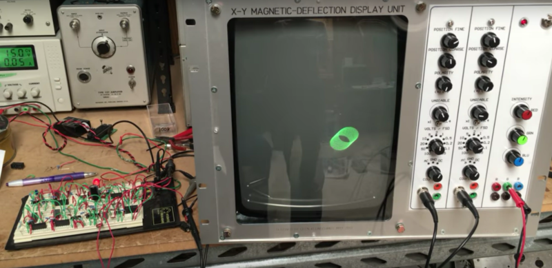
OK, it takes quite a large handful of op amps and considerable cleverness to model everything in this simple system, as [Glen Kleinschmidt] discovered when he undertook to recreate a four-decade-old demonstration project from AEG-Telefunken. Plotting the position of an object bouncing around inside the virtual box is the job of two separate circuits, one to determine the Y-coordinate and bouncing off the floor, and one to calculate the X-coordinate relative to the walls. Those circuits are superimposed by a high-frequency sine-cosine pair generator that creates the ball, and everything is mixed together into separate outputs for an X-Y oscilloscope to display. The resulting simulation is pretty convincing, with the added bonus of the slowly decaying clicks of the relay used to change the X direction each time a wall is hit.
There’s not much practical use, but it’s instructional for sure, and an impressive display of what’s possible with op amps. For more on using op amps as analog computers, check out [Bil Herd]’s “Computing with Analog” article.
https://www.youtube.com/watch?v=9dw3aDMlCso
Thanks to [Frank] for the tip, and for helping [Glen] patch the dodgy Google translation.


The invention of the Op-Amp has to be among the most significant developments in electronics. They make the impossible possible.
This brings back memories of my undergrad circuits class, where one of our lab assignments was to build a similar circuit (we only had to consider the vertical motion, and left the ball as a dot). Was a neat project, incredibly satisfying to see a pile of opamps perform such a nontrivial calculation. Also, since we used analog switches instead of relays we had to add an additional speaker to click when the ball hit the floor.
the magazine article that started my obsession with Lunar Lander, started with one of those reprint A5 magazines that had an analog lunar lander circuit.
A meter for altitude, vertical velocity and fuel, there was a whole check list to go through to set initial altitude, zero the velocity and set fuel level.
I do have some vague memories from my youth of an magazine article featuring a design of an analog lunar lander game. I can’t find anything relevant by googling except some class notes for building a simplified game.
It’s possible to make an op-amp selectively inverting or non-inverting so you don’t need the relays.
How would you recommend doing that?
It sounds very useful.
Tried to find the curcuit online, but a quick search showed none. So I try to explain with words. Take a voltage subtraction curcuit. Like this:
http://www.elektronik-kompendium.de/sites/slt/schalt/02101531.gif
1. Connect both inputs together.
2. Set every resistor value the same.
3. Substitute R4 for a switch (mechanical, electronic doesn’t matter es long es it allows current in both directions).
Case 1. Switch is open:
Since full input voltage is at the positiv input of op-amp the op-amp acts as a voltage follower (gain +1).
Case 2. Switch is closed:
Since positiv input of op-amp is at ground potential the op-amp acts as an inverting amplifier (gain -1).
Disadvantage: Not freely selectable gain between inverting and non-inverting amplifier configuration.
Advantage: Electronic switch (like FET) allows switch states between zero ohm and infinity ohms and therefor a gain between +1 and -1 including 0.
This was the basis of an article I wrote back in ’68. It was based on using the EAI TR20 analog computer. It was published in the American Journal of Physics in ’69. Unfortunately it’s not available on-line. For me it would be interesting to see if there is a link from my work to this.
Bernd Ulmann explains the process involved in converting a mathematical model to one of these circuits in the following video.
https://www.youtube.com/watch?v=H_4bFgYReq0
Here is some information on analog computers and a schematic for a similar circuit that I’ve built.
http://theanalogdog.com/Wiki/doku.php?id=analog_computers
http://theanalogdog.com/Wiki/lib/exe/fetch.php?media=analog_bouncing_ball_circuit.pdf
Here is some information on analog computers that I’ve complied, as well as my work on a similar bouncing ball circuit.
http://theanalogdog.com/Wiki/doku.php?id=tennis_for_two
http://theanalogdog.com/Wiki/lib/exe/fetch.php?media=analog_bouncing_ball_circuit.pdf
https://youtu.be/JETQDHeVOwQ
nice.
Analog computing? Autor, keep going and after few months you’ll be ready to make game “Tennis for two”. https://www.bnl.gov/about/history/firstvideo.php
If memory serves, a damped harmonic oscillator takes 3 op-amps. 2nd order DEQ, so two to integrate and one for some sums. When the LM308 came out, you could run the solution so slowly that the circuit could be used as a filter for seismic signals down to .01 Hz.