With almost 8 billion souls to feed and a changing climate to deal with, there’s never been a better time to field a meaningful “Internet of Agriculture.” But the expansive fields that make industrial-scale agriculture feasible work against the deployment of sensors and actuators because of a lack of infrastructure to power and connect everything. So a low-power radio network for soil moisture sensors is certainly a welcome development.
We can think of a lot of ways that sensors could be powered in the field. Solar comes to mind, since good exposure to the sun is usually a prerequisite for any cropland. But in practice, solar has issues, the prime one being that the plants need the sun more, and will quickly shade out low-profile soil-based sensors.
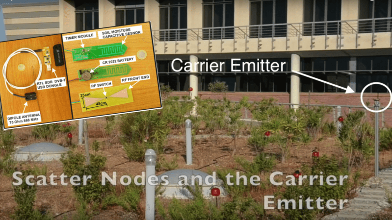
That’s why [Spyros Daskalakis] eschewed PV for his capacitive soil moisture sensors in favor of a backscatter technique very similar to that used in both the Great Seal Bug and mundane RFID tags alike. The soil sensor switches half of an etched PCB bowtie antenna in and out of a circuit at a frequency proportional to soil moisture. A carrier signal from a separate transmitter is reflected off the alternately loaded and unloaded antenna, picking up subcarriers with a frequency proportional to soil moisture. [Spyros] explains more about the sensor design and his technique for handling multiple sensors in his paper.
We really like the principles [Spyros] leveraged here, and the simplicity of the system. We can’t help but wonder what sort of synergies there are between this project and the 2015 Hackaday Prize-winning Vinduino project.
[via RTL-SDR.com]


So, RF retroreflectors? Am I understanding the text correctly by interpreting that eliminating PV (power source) was possible because the RF retroreflector transmission technique is much less power-hungry and powering a transmitter? So the RF isn’t supplementing power at all, rather reducing the load such that a battery is sufficient?
Yup, unless “BAT” is a small fury creature turning a dynamo.
http://oi63.tinypic.com/25kiqte.jpg
Also see that non-inert cooper based sensor, how long do you think that will stay stable in moist soil that is rich in humic acid?
Pretty sure this is a proof-of-concept, so he took the approach that’s easiest to fabricate. A production system would need everything ruggedized.
This should fix it,
https://www.youtube.com/watch?v=7DIXFA95x4M
i want to take this opportunity to make a confession:
i am 37 years old and still learn why things wear out over time by deploying prototypes into my real life
HAD is full of giants, fee free to save yourself much time and effort by standing on their shoulders.
HAD is full of people that think they are giants. You will be better of doing research on an appropriately peer reviewed site.
I am a 63-year-old prototype human, and am pretty thoroughly worn out. I can tell you that it’s not the years, it’s the miles.
Yep, some demonstrated it with WiFi and it needs power in the uW range instead of many many mW.
http://iotwifi.cs.washington.edu/
There is an even more advanced version reaching higher data rates web.stanford.edu/~skatti/pubs/sigcomm15-backfi.pdf
And another UW link to do LoRA backscatter. Hundreds of meters to km of range with microwatts at the backscattering side.
https://www.usenix.org/conference/nsdi21/presentation/katanbaf
I’m not sure I understand why capacitance is being used rather than conductance.
Because a capacitive sensor can be sealed up, thus making it durable. A conductive sensor will get eaten away by chemicals in the soil.
That sensor doesn’t look sealed to me, and anyway if it were sealed how would detect anything
The dielectric constant of the medium determines the capacitance of the electrodes. The dielectric constant of water is about 80x that of air or vacuum. Capacitive sensing is exquisitely sensitive to water content, and permits sealing the electrodes.
You may want to read up here: https://www.instructables.com/id/Comparison-of-Capacitive-Soil-Probes/
Neither of these measurements are as good as using a neutron probe if you want absolute volumetric measurements. It is very difficult to get a good reading with other probes due to the interface with soil and that you can’t get significant penetration around the probe. If you take one of the capacitive probes and place the palms of your hands on it while measuring, you will notice that the reading dramatically change the harder you press. Now imagine installing this in the soil without disturbing it in order to make representative soil water content measurements. At best, the capacitive probes will give you a good relative measurement for knowing when to water, assuming you have them placed at multiple depths.
Capacitance for moisture content (dielectric permittivity) … Conductance for ion measurement (salts and the like). Would be great to measure nitrates (hard) and ph (very hard insitu).
Or you know, you could leverage the synergy of upcycled simplicity by using Enocean.
Could somebody explain what the “SW IC” on the schematics is and what funcion it provides, please?
Some kind of diode? I want clarification as well.
The paper is here http://www.telecom.tuc.gr/~aggelos/files/mtt_2016.pdf
All they say is ” As depicted in Fig. 4 (arrows), the parallel capacitors (Cp and Csm) are periodically charged and discharged through R2 and an electronic, singlepole single-throw (SPST) switch (SW). The SW is open when timer output is in logic “low”, so there is no leakage current through the SW loop”
So it sounds like a simple PMOS to me….
Scratch that, should be an NMOS, which would not work directly.
So, take one from here http://www.ti.com/lsds/ti/switches-multiplexers/signal-switches-products.page?familyAliasId=1203279#p1143=1:1 SPST
http://www.ti.com/lit/ds/symlink/max4594.pdf example