Line Followers are a tried-and-true type of robot; both hardware and software need to be doing their job in harmony in order to be successful at a clearly defined physical task. But robots don’t always have microcontrollers and software, as [Mati_DIY]’s zero programming analog line follower demonstrates.
For readers used to seeing a Raspberry Pi or Arduino in almost everything, an analog robot whose “programming” exists only as a harmony between its discrete parts can be an eye-opener as well as an accessible project. A video of the robot in action is embedded below.
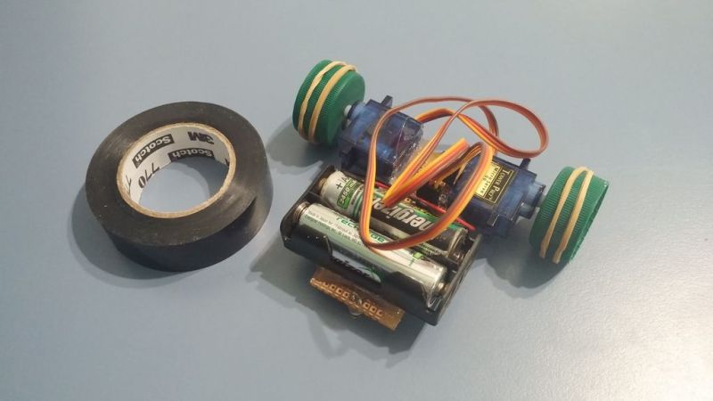
[Mati_DIY]’s design uses two CNY70 reflective sensors (which are essentially infrared emitter/phototransistor pairs) and an LM358 dual op-amp. Together, the sensors act as two near-sighted eyes. By using the output of each sensor to drive a motor via a transistor, the presence or absence of the black line is directly and immediately reflected by the motion of the attached motor. The more black the sensor sees, the more the motor turns. Electrically, that’s all that happens; but by attaching the right sensor to the left motor and the left sensor to the right motor, you get a robot that always tries to keep the black line centered under the sensors. Playing with the spacing of the motors and sensors further tweaks the performance.
The motors in [Mati_DIY]’s robot look like 9g servos, but if so they must be modified for continuous rotation to work in this design. The modification is a classic robotics hack, but nowadays it’s possible to purchase units already in continuous rotation format.
If you find this direction of robotics interesting, you might want to look into the various BEAM robotics projects we have featured over the years, like this tumbler or this solar-powered Turbot hybrid. For an even more complex take on a microcontroller-free line follower, be sure to check out this slick-looking robot that features a hardware implementation of PID.


Been there, done that. No need for op-amps, 1 flip-flop is enough. Obviously you also need 1 potato as camera :P https://www.youtube.com/watch?v=yNyRQOa8_iE
The real pros just wire photoresistors straight into the motors. Using silicon is a luxury not everyone is afforded!
I always wanted to make one using the internal feedback circuitry in a servo for the tracking, it seems like you could probably replace the position feedback with a voltage divider made out of a pair of photoresistors (with direction swapped for the right and left servos). You need to crack open the servos to convert them to continuous rotation, why not use their electronics too.
i would love to see a teardown of one of these japanese “micromouse” robots solving mazes. These things are incredibly fast, I wonder how they get enough friction to accelerate like that, and how they accomplish such good position tracking.
https://www.youtube.com/watch?v=ExW_rxKdNJE
that video only shows the last round after it did a “solve run”. and of course it is lightweight, but i bet there’s some mechanical secrets to getting this performance.
also sorry for using all that pixel real-estate with that youtube video ..
the article is a good example of an hysteresis controller or bang–bang controller.
I bet it has incredibly sticky tires. It moves like those old 1:64 scale ZipZaps RC cars RadioShack used to sell.
And a steel table, with a button magnet to pull it down.
“Zero Brains” ???
There is a hint in the fact that it is closed loop feedback.
It’s a classic PID using both analogue and mechanical computing.
Yes, it is a simple state machine, it’s outputs are logical responses to it’s inputs. It is a “brain”.
loving the bottle caps with rubber band wheels.
The LED front “Wheel” is a nice solution for a junk box build.
When I was in yr7 there was a project in an electronics magazine to build a line following car ( all analog control similar to this one one ) but instead of differential drive it used one motor for drive and another actuated the steering.
I so wanted to build one but didn’t have the skills or know suitable people to help make it a reality or have access to the parts. :(
30years later I still haven’t done it
I’ve seen these designs before, they are neat…Nice take on using recycled things instead of buying new stuff.
Hah! This whole time I thought continuous-motion-modified servos still used the PWM/H-Bridge circuitry… Was trying to imagine how PWM’d be done with op-amps.
So basically the motor’s directly-connected and the servos are basically nothing more than gear-boxes.
That opens some doors for those of us lacking servos. One time I found a supply of old Mac/Apple floppy-drives for real cheap, which I bought specifically for their highly-reduced disk-eject gear-boxes. Or old remote-control cars with differential drive, like FastTraxx… maybe even hovercrafts… Or tiny-bots with motor-shafts directly touching the surface.
I wonder if the op-amps are necessary, maybe the transistors alone would be enough amplification?
Great weekend project.
In his article he says that any transistors will do but the ones he used has a relatively high Vce for a small signal transistor. Other transistors with a lower Vce would probably pop because of the back EMF from the motor. The circuit needs some diodes from collector to emitter to protect the transistors.
No brain as in no “actual” algorithm. No sequence, no neural network. No actual code.
The only thing that Line Follower is doing is trying to keep both of the sensors to give the same value. Which is the same as just any regulator. It’s just “V+ = V-” of an op-amp.
It’s a hybrid analog / mechanical PID computer.
The Integral component comes from the motor driving voltage / distance between the wheels and distance to the front sensor which all play a part if how quickly the movement away from the edge of the line is as a response to the previous PID result.
The Proportional is controlled by the op-amp and the comparison between the distance between sensors and the width of the line form the derivative.
All of these things can be measured or calculated to get the actual algorithm you mention.
Things don’t have to have a micro-controller or CPU to be a computer or make calculations.
Here’s another no-code PID controller –
http://www.ecircuitcenter.com/Circuits/op_pid/image002.gif
Danm, transparent colors!
https://cdn.hackaday.io/images/2301421489890550124.jpg
The simplest line follower robot I know is “Emily” from Popular Electronics, March 1962: only 1 transistor and 1 relay.
I found about it from the comments posted here https://hackaday.com/2016/09/27/line-follower-with-no-arduino/
(schematics available in the comments section, first 2 links)
Pretty cool ! I did something similar when i was high on MSP430s . Used PID things though. The motors were i guess from CD ROMs my Aunt scrapped. Worked Okish. I added a bead as a castor and used a Li-Ion battery for the entire thing.
//embedr.flickr.com/assets/client-code.js
Pretty cool. I made something similar back when i was high on MSP430s. Used motors from CD ROMs my aunt scrapped. The wheel was also from the CD Rom eject assembly. Worked okay-ish. Used Li-Ion battery for power.
//embedr.flickr.com/assets/client-code.js