A few weeks back, we talked about the no-nos of running I²C over long wires. For prototyping? Yes! But for a bulletproof production environment, this practice just won’t make the cut. This month I plucked my favorite solution from the bunch and gave it a spin. Specifically, I have put together a differential I²C (DI²C) setup with the PCA9615 to talk to a string of Bosch IMUs. Behold: an IMU Noodle is born! Grab yourself a cup of coffee and join me as I arm you with the nuts and bolts of DI²C so that you too can run I²C over long cables like a boss.
What’s so Schnazzy about Differential Signals?
There’s a host of ways to make I²C’s communication lines more noise resistant. From all of the choices we covered, I picked differential signals. They’re simple, fairly standardized, and just too elegant to ignore. Let’s take a moment for a brief “differential-signals-101” lecture. Hopefully, you’re already caffeinated!
Suppose we have two devices that want to communicate over a single wire. To get the conversation started, we run a single-ended signal over a long cable from one device to another. Just imagine a lengthy hookup wire between breadboards. Let’s assume the sender sends a digital output (logic 0 or logic 1), and the receiver expects to receive a digital input (logic 0 or logic 1).

Now, suppose we add some electromagnetic interference (EMI) by introducing a nearby motor and turning it on. From Faraday’s laws, a changing magnetic field from the motor will induce a voltage along these wires, which we’ll pick up as a voltage spike.

If these spikes are strong enough, the receiver will treat these signals as digital inputs, even though they’re not supposed to be there in the first place! What happens? Since we’re not prepared to receive these signals, it’s undefined, and anything goes! Our encoders will read random numbers, steppers will take bonus steps, buttons will read: pressed, rockets will blast off, satellites will fall out of orbit, and we are so fired.
Mayhem aside, let’s now hookup our sender and receiver along a differential signal.

In this setup, the receiver reads the difference between the top and bottom channels. The sender passes a logic 1 by applying equal-and-opposite voltages on both lines at the same time. Here lies the beauty of the differential signals: if we assume that both of our signals are being affected by the noise source equally, then they will both pick up an equal amount of noise. Since there’s no difference between the noise signal across the two channels, the receiver reads nothing. The noise is invisible!

Remember: we’re assuming both signals are being affected by the noise equally. To make that assumption, we need to space our differential pair wires as closely as possible together, which means either ribbon cable (like LVDS) or, even better: a twisted pair (like USB or Ethernet).
The Beginnings of an IMU Noodle
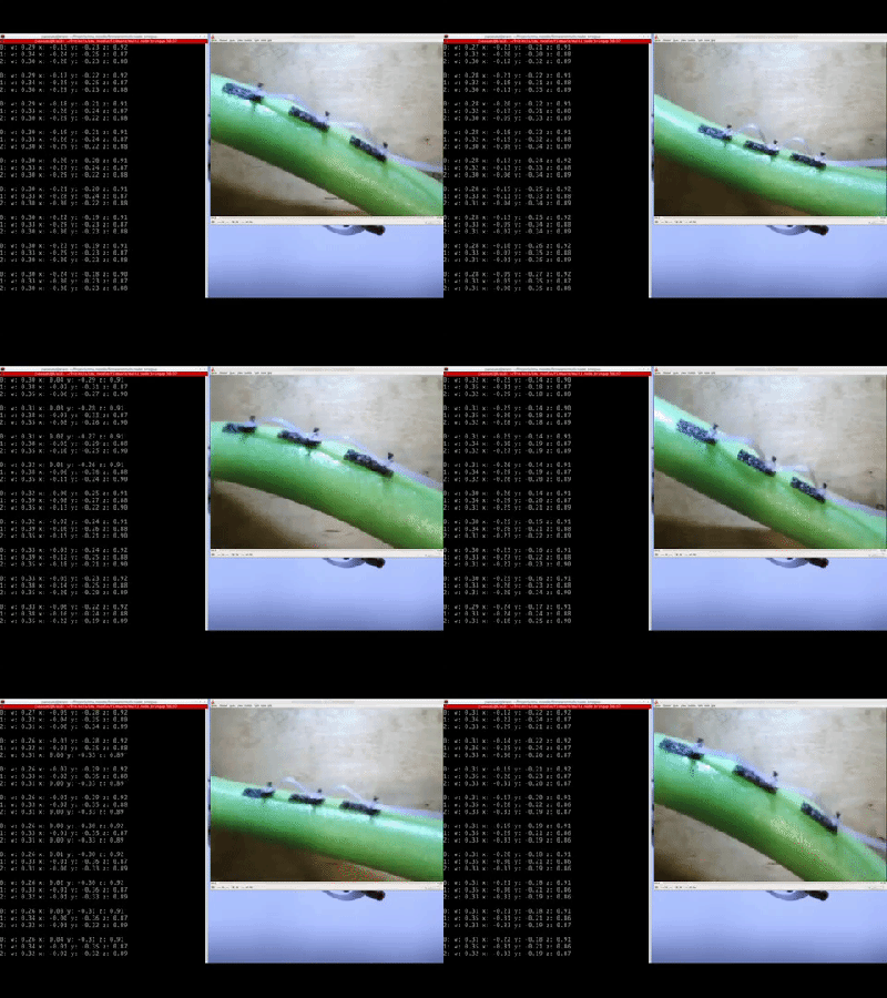 To get everyone jump-started on the DI²C bandwagon, I started tackling a project to showcase DI²C at its finest. I’ve been dying to build an IMU Noodle for almost three years now. It’s only now with both DI²C and the BNO055 that most of the groundwork has been put down; all I need to do is put together the pieces in one clean package, plus a bit of math. My take on this project will be a cluster of uniquely addressable nodes tied together over DI²C. I’ll save the IMU Noodle details for a later post. For now, let’s focus of the nuts and bolts of DI²C that runs along each node and makes this project possible.
Getting Cozy with DI²C
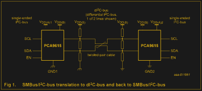
In a nutshell, DI²C isn’t too complicated. We’re all pretty familiar with conventional I²C’s SDA and SCL signals. The PCA9615 simply splits each signal into two differential pairs for a grand total of four communication wires. Any chip that wants to jump onto the DI²C bus first needs to convert it’s SDA and SCL lines into the corresponding Plus and Minus differential pair signals: DSDAP, DSDAM, and DSCLP, DSCLM. After that, communication can begin as normal with no software changes.
One last hiccup: the start and finish of the actual cable that carries the DI²C signal needs to be populated with termination resistors. These resistors are specced to match the characteristic differential impedance of the cable itself. (Find this value in your cable datasheet.) Before you all go home and try building systems without them, hear me out: these resistors are necessary. Without them, the signals that run down the wire will reflect back up and down repeatedly until they dissipate. Of course, we certainly can’t have bogus copies of old data interfering with new data. Simply adding the proper value termination resistors eliminates this problem.
Setting up a DI²C Configuration
The PCA9615 has a few options for setting up a DI²C bus. I chose the multi-drop bus configuration.
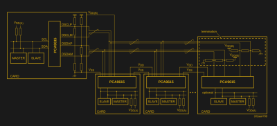
In the setup above, each “card” has a local I²C bus which hooks up to a cable that forms a shared DI²C bus. A PCA9615 on each card does the back-and-forth conversion between the open-drain side and the differential side. Together, these cards form one large bus, which means that all addresses must be unique. I opted for this solution for it’s simplicity; each IMU lives on a dedicated board and relays its data back to one master at the start of the cable. At the end of the cable, the final IMU node also terminates the DI²C signal with the proper termination resistors.
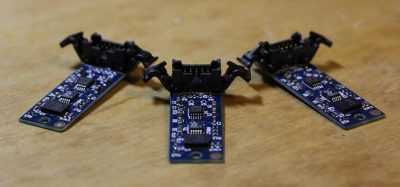
This configuration has one main benefit. Except for the last node, each node has the exact same topology. And since PCBAs usually come cheaper by-the-panel, having one design made ten to twenty times is far cheaper than fabbing multiple designs. Lastly, to handle that edge-case where the final board needs termination resistors, I put optional footprints for them on each IMU Node, but only the last board has them populated.
When it comes down to the actual discrete parts for setting up a DI²C node, it’s pretty simple.
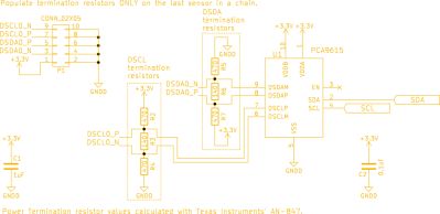
This schematic is just the jumble of datasheet recommendations on one page, with some bypass caps for good measure. Keep in mind that the termination resistors should only be populated on the first and last node of the DI²C chain. For all other nodes, they should be omitted.
Side note: this chip does have the option of running the DI²C signal and the local I²C circuitry at two different voltages, allowing small voltage offsets across boards, but mine are joined together for simplicity of wiring.
As for what value termination resistors to choose–don’t sweat it! There’s an app-note for that! Specifically, given (a) the differential impedance of the cable we’re using and (b) the supply voltage of the differential lines, AN-847 will take us through the calculations for proper bus termination resistors.
Finally, to route the data out of the DI²C cable and back into a conventional microcontroller, I spun a vanilla PCA9615 breakout. This board is a duplicate of the DI²C circuitry in the IMU Node schematic, and it’s the first node on the DI²C chain, hence: it gets termination resistors.
Pro-ing up our Cables:
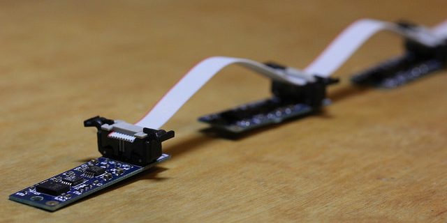
OK, so that multi-drop bus looks nice on paper, but how do we translate that concept into a cleanly executed network of boards? By far, my best answer has been teeny ribbon cable and (ridiculously cute) ribbon-cable connectors and sockets. Ribbon cable has the benefit that we can simply crimp as many intermediate connectors anywhere along its length and the pinout will be identical across each connector.
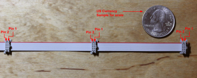
That’s exactly what I did here, where this ten-pin ribbon cable runs all four differential pairs (interleaved with GND signals), with the remaining wires for the supply voltage. As for those connectors, for their size, they’re ridiculously easy to attach to the mating cable. One squeeze in a vise, and we’re connected! (Ha! Take that, nefarious JST SH Connector! Never again will I crimp you into one of my side projects!)
While ribbon cables aren’t twisted pairs, which would be the ideal way to run these differential signals, the 0.025″ pitch on this ribbon cable is sufficiently closely-spaced that I’ll call it “good enough.”
Take DI²C Out for a Spin
That about sums-it-up for a DI²C implementation. Not too tricky, right? Now go forth, and may all your long-distance I²C projects shine with a savvy communication layer and some pro wiring!
If anyone’s dying to get started with some example files, I’ve dropped the PCB design files (KiCAD) and firmware on Github. May they give you the after-hours kick to jump-start your next long-distance DI²C project! And, of course, if you build anything fun, write back to us. We like that :)



This is what CAN bus is for… ;)
vim! emacs! I2C/SPI/CAN/XYZ argument may now commence.
DAE Dallas ^H^H^H Maxim 1-Wire?
No, CAN requires a lot more than I2C does, even differential I2C. For instance, the slaves are asynchronous, so they don’t need a clock source at all (internal to the chip or otherwise).
For SPI, there’s also a nice chip from Linear that converts SPI to an isolated twisted pair interface (LTC6820) so if you’ve got 4 or less slaves, you could use a bunch of those guys and Ethernet cable runs (take 1 pair for each), even in a daisy chain if you wanted (have each board take pair 1 and pass out pair 2->4 one pair up).
Obviously more complicated than this setup, but also significantly more capable (up to 10 M total length, complete isolation).
CAN is likely overkill, but RS485 is made exactly for this application …
No, it isn’t. RS-485 is just an electrical standard, not a protocol. A lot of people say “RS-485” when they actually mean “a UART over RS-485,” so if that’s what you’re talking about, again, that requires more brains and has less flexibility than I2C. Need to agree on a baud rate, both sides need to have a clock of their own, no way to have slaves have different communications capabilities, etc.
“RS-485, also known as TIA-485(-A), EIA-485, is a standard defining the electrical characteristics of drivers and receivers for use in serial communications systems”
Maybe we can consider “UART over” redundant?
They actually mean “some data over a protocol over a UART over RS-485 over some twisted wires”.
Also, there are some serial protocols specifically designed for this. What about Modbus?
No, it’s not redundant. RS-485 is a signaling standard, like any signaling standard (LVDS, ECL, etc.). Saying it’s used for ‘serial communication systems’ doesn’t say anything about the actual bit encoding on the bus. It could be anything. UARTs use a start bit for framing, and then some number of bits of data, addressing, or parity, and then a stop bit (which actually just returns the line to idle, and defines the minimum time between transmissions). But you could run data Manchester-encoded with sync words and packeted data if you felt like it.
I2C is a complete communications standard, with a defined physical layer and enough protocol layers that you can make a generic I2C slave that any transmitter can talk to. There are plenty of protocols that define protocols *on top of* I2C to improve it (routing, error correction, elimination of bus stall, etc.) – e.g. SMBus, IPMI, PMBus, etc. There’s a huge difference between the two.
It is redundant in any informal discussion, if someone says RS485 without further detail we assume uart. It just annoys you.
What bugs me is when people says lvds to anything interfacing any kind of display.
Let me be clear: the original point was that RS-485 was made for long-haul multidrop communication between devices moreso than differential I2C. It wasn’t. It was made for long-haul multidrop signaling. The communication part is completely left out of the standard: there’s no addressing, no collision detection, no standard signaling rate, no standard bit formatting, etc. Nothing.
If you expand it and say “oh, I meant a UART over RS-485,” which is how RS-485 is normally implemented, that solves only part of the bit formatting issue. It doesn’t fix addressing, collision detection, signaling rate, etc., all of which is handled in the I2C specification already. So a UART over RS-485 is definitely not made for something like this.
You could extend that, and say, “what about Modbus?” or some other higher-layer protocol, and *those* are made for something like this – except those implement collision detection/addressing at a higher level than I2C, so I2C is going to end up being more efficient.
You’d be much better off saying “CAN is made for this” but as I said elsewhere, CAN is much, much more complicated for a pure slave to implement than I2C.
CAN is a protocol that runs over RS485…
I hate I2C, it has so much CPU overhead, you have to “baby sit” each byte to ACK or NAK, STOP, RESTART, etc…
The CAN controller take care of the protocol for you.
Just give it the address and data.
It takes care of the bit stuffing, address collision, check sums, retries, etc…
I think I just get used to Microchip dsPIC parts, where you can setup the peripherals to use DMA… except I2C, which then feels like you are bit banging the protocol. Since all the I2C peripheral does for you is shift out a byte. ;P
agreed canbus is a lot better and you CAN (get it) make your own protocols. having a clock run down the wore is not a benefit, it’s actually a liability. I would much rather have my data flow without the reliance on a clock so I can have more robust communications.
There is a reason it’s used in Ships, airplanes, Trucks, cars and motorcycles over Differential I2C and canbus is not hard to put in use Hell I have CAN running in an Attiny13
1) The complexity is at the master and design side. An I2C slave is harder than an SPI slave, but not a lot. Most importantly, you *don’t need an oscillator*. The clock’s provided for you. You’re thinking of it at the microcontroller level, not at the device level.
2) Get a better I2C peripheral. TI’s MSP430 eUSCI peripherals are extremely good, as are the ARM-based uC’s, for the most part. But the eUSCI peripheral is easily the best I’ve seen on any microcontroller.
I’ve been wondering about this, is rs485 eletrically the same as CAN? if so can i use a rs485/DMX based chip to listen to can data ? then use a micro like arduino to convert in human readable, i’ve wondered about this many time but too lazy to actually try it.
CAN is not RS484, it is true that some early CAN (ab)used RS484 transceivers but they were wired to use enable as data to get the CAN dominant/recessive states
Pat, do you know if there are any other offerings out there similar to the LT6820? I work with systems requiring a somewhat slow SPI bus that requires isolation and transmission over a cable. That part looks fantastic for what I need, but it could be a little faster. Anything out there you know of?
The LTC6820 is the only one I know of. It’s relatively slow (for SPI) because the isolated portion is running much faster – the pulses there are on a 50 ns timescale. It’s a really cheap chip for what it does.
SN65LVDT41PW
SN65LVDT14PW
might do the trick
Derp, i dont think the suggestion I made is actually isolated, just fast differential spi
ISO1541DR from master or gnd 1 to gnd 2 (how ever you wish to conceptualize) then rock the chip above for diff signaling. dont forget pullups between the iso1541 and PCA9615
Thanks Pat. I’ve been doing a lot of SPI stuff and the LTC6820 looks like it’ll give me some much needed distance.
Well, the problem with using simple ribbon cable is that, well, it isn’t actually 100 ohm differential. So you won’t get the length/speed out of it that you normally would. Twist and flat would work. Probably don’t need to intersperse grounds if they’re properly twisted pair, so the remaining 3 pairs could be used for power/ground.
The same NXP chips also work surprisingly well for running ARM SWD over long cables.
Why would you have to run SWD over long distances? You can just put the programmer near the board and then use USB extension cables to reach the computer. (USB is differential, too. And this solution needs no extra chips.)
Reasons.
usb 2.0 is 5 meter max without repeaters/hubs in the chain.
You can get flat, twisted pair, ribbon cables, but the distance between the areas where you can crimp is usually pretty big compared to what was shown here. 3M certainly makes it and probably others too.
Didn’t know this PCA9615 part before. Thanks for that… there are a lot of new possibilities
I thought that the terminator resistor was for biasing the differential pair mainly, like in the CAN bus.
That’s the wrong cable (article picture) for a differential signal. It should be twisted pairs like CAT5 or two coaxials.
Great project, good write up, thanks.
Neat! I’ve been wondering about differential transcievers for a variety of signals. Specifically, the dreaded WS2812 protocol. I suppose that the LTC6820 mentioned that Pat above could work, as the WS2812 looks close enough to SPI. But otherwise, what are other similar transceivers that are good to know about? Also, why are they associated to a protocol? Couldn’t they be made generic? Or is it just for market targeting?
If you’re not forced to use the WS2812, you might want to consider switching to the APA102. They use standard SPI and have a 50 times higher PWM rate.
Have not tried it, but your typical RS485 should get you a pretty long way with the <1Mbps signals required for the WS over ethernet.
https://www.maximintegrated.com/en/app-notes/index.mvp/id/3884
Also, each WS led regenerates the signal and can drive up to 3m (?) of cable after it. So, a string with a LED every 3 meters is much cooler :D
Gigabit Ethernet uses two pairs for transmit and two pairs for receive so that’s 500Mb/s per pair, so I would expect you could get much better that 1Mb/s with Gigabit cable or even CAT5 and differential signalling even at 5 Volts.
And here you are wrong. There are multiple gigabit ethernet standards (see wiki, seems comments with more than one link are rejected).
The most popular (but not the first first) is 1000BASE‑T http://www.ieee802.org/3/ab/public/nov97/geoff1.pdf
It transmits and receives on all 4 pairs and uses multi level signaling. This means it requires only 125MHz of bandwidth per pair which is why it can work with the cheaper CAT5E cable which you already have in most places already installed.
OK, so it’s only 250Mb/s per pair and CAT5 is only 50Mb/s (full duplex) so how does that make me wrong when I say achieving a measly 1Mb/s should be easy over CAT5 cable.
There is 1.5 orders (decade) of difference.
I meant you were not right about how ethernet works, not about pushing 1Mbps over cat5.
My wonder is what about the bidirectionality of the I2C lines? SPI has dedicated input and output lines, but SDA and SCL pins are often singular and bidirectional, both being able to pull down the line and read it. (and have it return when not pulled)
How is this conserved electrically here, through the conversion?
By having four voltage states of the signal line to represent the 2 binary states from each end.
From the datasheet, it seems the chips understand the situation and switch between reading the bus or driving it:
“Each node acts as both a driver and a receiver to allow bidirectional signal flow, but not at the same time. Switching from transmit to receive is done automatically.”
Just out of a curiosity: why not make the terminator as a separate entity plugged into a socket on every end of the cable? Like with teh old-school coaxial ethernet or SCSI, with resistors embedded into the connector body. Then all the IMU boards would be the same & could be plugged into the bus in any location. Of course this would require two additional connectors on both ends of the cable.
How are the PCA9615’s for power consumption? It seems like it would probably be fairly high driving all those termination resistors and bias currents. I am thinking of using them in a project but since it will be a battery powered application I am weary of the current draw. The datasheet doesn’t really spec real world currents for typical application circuitry.
Has anyone used USB C connectors /cables for DI²C? This sounds interesting to me, use the two differential Highspeed lines for SCL and SDA and also use the cable for powersupply.