[Ludic Science] shows us the basic principles that lie behind the humble boost converter. We all take them for granted, especially when you can make your own boost converter or buy one for only a few dollars, but sometimes it’s good to get back to basics and understand exactly how things work.
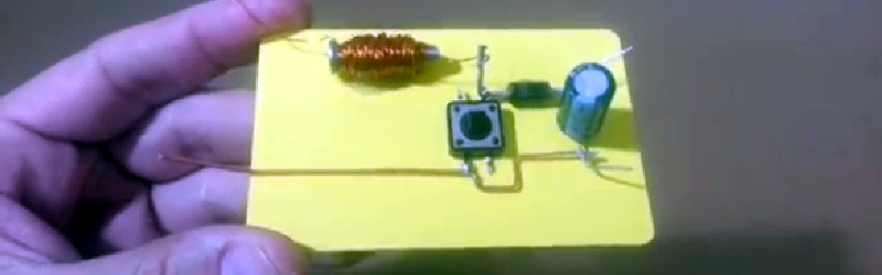
The circuit in question is probably as simple as it gets when it comes to a boost converter, and is not really a practical design. However it helps visualize what is going on, and exactly how a boost converter works, using just a few parts, a screw, enameled wire, diode, capacitor and a push button installed on a board.
The video goes on to show us the science behind a boost converter, starting with adding a battery from which the inductor stores a charge in the form of an electromagnetic field. When the button is released, the magnetic field collapses, and this causes a voltage in the circuit which is then fed through a diode and charges the capacitor a little bit. If you toggle the switch fast enough the capacitor will continue to charge, and its voltage will start to rise. This then creates a larger voltage on the output than the input voltage, depending on the value of the inductor. If you were to use this design in a real life application, of course you would use a transistor to do the switching rather than a push button, it’s so much faster and you won’t get a sore finger.
This is very basic stuff, but the video gives us a great explanation of what is happening in the circuit and why. If you liked this article, we’re sure you’ll love Hackaday’s own [Jenny List] explain everything you need to know about inductors.
(updated thanks to [Unferium] – I made a mistake about the magnetic field collapsing when the button is pressed , When in reality it’s when the button is released that this happens. Apologies for confusion.)


Very helpful and clear explanation.
I remember the first time a brushed motor design clicked for me– it was another one of these “wire wrapped around a nail” handmade designs, and it really helped me develop an intuition for the circuit.
Thanks Ludic!
Obviously there is so much more to a good boost converter and pointing this out would be the only omission from the video but as a basic example of how a boost converter works, this video is spot on.
Back in the days I was sat in the classroom learning electronics, spending five minutes demonstrating like this would have been worth more than over half hour of chalk and talk.
I thought it is the switch is closed to establish a current through the inductor and thus a magnetic field and then opening the switch looses this current leaving no current to maintain the magnetic field and the magnetic field colapses with nowhere to go except through the diode and capacitor (Whilst trying to achieve the highest possible voltage at said current determined by the ESR of the diode and capacitor). The larger the inductor (The more windings) the higher achievable voltage can be put on the capacitor due.
the way you put it is like a current flows (where?) when the switch is opened and the capacitor is charged when the switch is closed (Diode-inductor tap to GND so current flows to GND, not capacitor. So where is this charge in the capacitor coming from at the time no charge gets to the capacitor???)
Quote:
“starting with adding a battery from which the inductor stores a charge in the form of an electromagnetic field. When the button is pressed, the magnetic field collapses, and this causes a voltage in the”
That is unless it is a push to break switch, the article would need this noted to stop confusion.
There is no confusion. Did you watch the whole video?
I’m on about the article writeup, where is this field in the inductor when the battery is applied (no mention of the switch being pressed)
No current flow == no magnetic field (IRL a temporary field as the capacitor charges to Vbat-DiodeVdrop + switch capacitance).
Switch closes == full current flow through inductor(IRL with a curve buildup to max), blocking diode stops Capacitor discharging.
Switch opens == Magnetic field gets dumped on an open circuit and the field has nowhere to go so the voltage rises until a current flows (0.6v for diode and a little bit above the capacitor relative to V=IxR aka V= colapse current multiplied by ESR of the capacitor)
.
The article reads as though closing the switch allows the grounded inductor and diode to send current through to the capacitor, in other words sounds like the common sometimes fatal , “Measuring the current across mains with ammeter” Mistake
.
I’ll complain about the video when I watched it…. If I say nothing about the video, then it was good/correct/etc
Forgot to ask:
How do you get a magnetic field to form when there is no return to the power source across said magnetic field generator????
If all was needed to make magnetic fields is a coil on the positive terminal of a battery and the other swinging in air connected to nothing, then free-energy would be solved. We find a positively charged sheet of, say, plastic and dangle a load of coils off of those to “arvest teh fwee energhey!!!!”
How do you get your text to go yellow like that?
Magic, Just pure magic….or was it a hackaday hack??? Hackception???
Ok, I’ll give the game away:
Use an empty “a” attribute, I’ll remove the “<" parts and replace them with the "{"
to get the post to show properly:
{a}yellow text{/a}
Now it would be awesome to work out how to do other colours, however I’d guess the HTML sanitizer (Filter) would kick in and wipe out all the hard work (Stops hacking the site through scripting, else someone can throw in an onload() or two)
Let’s find out if other options work…
Didn’t work. How about this?…
So, I think its displaying it that way because it assumes the text is actually a hyperlink do to the modifier, and therefore color formats it. So maybe…
a[target] { background-color: white; color: red; }
Nope. How about this?…
a[target] { background-color: black; color: red; }
Still No. And this?
“How about this?
The video is very clear but, like Unferium said, the description in the post is clearly wrong!
It should read “When the button is *released*, the magnetic field collapses”.
Thanks I’ve updated this to reflect what you said. It was an honest mistake I typed the wrong thing, thanks for pointing this out.
Cheers, Sorry about the over-explaining, more targeted towards helping the readers… :)
No I’m glad you brought it up it was a silly mistake to make but it’s much better now it’s factually correct. The aim is to educate and if there are mistakes then they need fixed.
And if anyone is tempted to correct Jack’s English, “they need fixed” is perfectly grammatically correct and very common in Scotland (as compared to the Cambridge “need fixing”, or the universal “need to be fixed”).
Can’t reply directly Jim but I didn’t know that was a thing, Thanks I love learning little things like this.
Sweet! good stuff for a student like myself
I also found the boost converter analogy with water from Cody very lively
https://www.youtube.com/watch?v=bgEvNCfDzzs
Well done. Always good to see things from a different perspective
This was a really great demonstration, but am I the only one who kept hearing Dolan Duck?
Quite frankly, both the explanation in the video and the explanation here make my power electronics hurt. The magnetic field doesn’t collapse nor does the current when the switch is opened. That’s exactly the point of the boost converter: the inductor makes the current (or the magnetic field) decay slowly. When the button is released the current “finds” a better path and flows through the diode. The current immediately before and after the switch is opened is exactly the same. A way to understand why this happens is to imagine the switch as a variable resistance that smoothly goes from 0 to infinity when it is opened. As the resistance increases, the voltage across the switch increases and eventually the voltage is high enough to make the diode conduct, which makes the current flow through the diode rather than through the switch.
You may not like this any better, but my own personal explanation for it is that inductors oppose changes in current by creating voltage. Likewise, capacitors oppose changes in voltage by sourcing or sinking current.
On the contrary, that’s a very legitimate way of explaining it.
The best way for me to understand what happens when the switch opens is to consider a small capacitance across the switch whose voltage is clamped when the switch is closed and released when it opens. After the switch is opened the current from the inductor can seamlessly commutate from the switch to the capacitor. Hence the capacitor is charged and its voltage will rise until it reaches the output voltage and the diode starts to conduct. That’s it.
A couple of things… One more nit picky thing but you should underrate the voltage on electrolytic caps. I believe the in the video the cap is rated at 100V. He had over 140V on that cap. Probably not the best demo.
Secondly, and bigger, it is important to remember that just like everything else in life, you don’t get something for nothing. You will get somewhat less than the same amount of watts out that you put in. You have the diode drop, the parasitic resistance in the inductor and the parasitic resistance in the cap. Pout will always be somewhat less than Pin.
On the flip side, I never really considered it before, but it is interesting to note that you can get that much of a boost out of a circuit with a simple mechanical switch. That might be useful for something down the road where you need semi high voltage at low current.
You’ll probably find that the voltage it settled at above 140v is due to arc-over of the capacitor, the voltage was too high and breached the electrolyte+separator. The other possibility is that is how much energy in the magnetic field during the cycle. repeat with a high voltage capacitor, 450v to 600v, and press said switch a good few times more, measure voltage, Should be higher in theory, if not then that is the inductor limit due to # of turns. add more turns or reuse a relay/solenoid coil winding, repeat experiment.
Thank you for taking the time to create and post this tutorial. You did an excellent job.