How hard can it be to create your own inductors? Get a wire. Coil it up. Right? Well, the devil is definitely in the details, and [Nick] wants to share his ten tips for building “the perfect” inductor. We don’t know about perfect, but we do think he brings up some very good points. Check out his video below.
If you are winding wire around your finger (or, as it appears in the video, a fork) or you are using a beefy ferrite core, you’ll find something interesting in the video.
A couple months back, [macona] got his hands on a 300 watt Rofin CO2 laser in an unknown condition. Unfortunately, its condition became all too known once he took a peek inside the case of the power supply and was confronted with some very toasty components. It was clear that the Magic Smoke had been released with a considerable bit of fury, the trick now was figuring out how to put it back in.
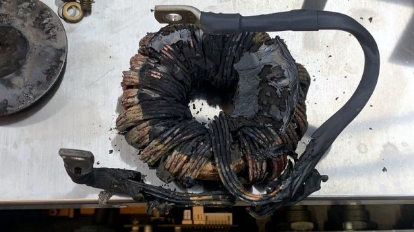
The most obvious casualty was an incinerated output inductor. His theory is that cracks in the ferrite toroid changed its magnetic properties, ultimately causing it to heat up during high frequency switching. With no active cooling, the insulation cooked off the wires and things started to really go south. Maybe. In any event, replacing it was a logical first step.
If you look closely, you may see the failed component.
Unfortunately, Rofin is out of business and replacement parts weren’t available, so [macona] had to wind it himself with a self-sourced ferrite and magnet wire. Luckily, the power supply still had one good inductor that he could compare against. After replacing the coil and a few damaged ancillary wires and connectors, it seemed like the power supply was working again. But with the laser and necessary cooling lines connected, nothing happened.
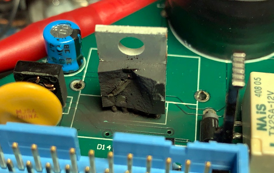
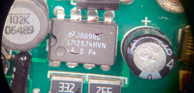
A close look at the PCB in the laser head revealed that a LM2576HVT switching regulator had exploded rather violently. Replacing it wasn’t a problem, but why did it fail to begin with? A close examination showed the output trace was shorted to ground, and further investigation uncovered a blown SMBJ13A TVS diode. Installing the new components got the startup process to proceed a bit farther, but the laser still refused to fire. Resigned to hunting for bad parts with the aid of a microscope, he was able to determine a LM2574HVN voltage regulator in the RF supply had given up the ghost. [macona] replaced it, only for it to quickly heat up and fail.
This one is slightly less obvious.
Now this was getting ridiculous. He replaced the regulator again, and this time pointed his thermal camera at the board to try and see what else was getting hot. The culprit ended up being an obsolete DS8922AM dual differential line transceiver that he had to source from an overseas seller on eBay.
After the replacement IC arrived from the other side of the planet, [macona] installed it and was finally able to punch some flaming holes with his monster laser. Surely the only thing more satisfying than burning something with a laser is burning something with a laser you spent months laboriously repairing.
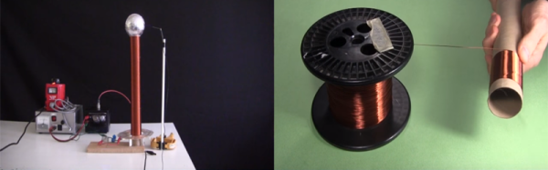
YouTuber [RimstarOrg], AKA Hackaday’s own [Steven Dufresne], shows how to make a DIY inductor for a specific inductance. This is obviously a great skill to learn as sometimes your design may call for a very accurate inductance that may be otherwise hard to find.
Making your own inductor may seem daunting. You will have to answer a few questions such as: “what type of core will I use?”, “how many turns does my coil need?”, or “how do I calculate these parameters to create the specific inductance I desire?”. [RimstarOrg] goes through all of this, and even has a handy inductance calculator on his website to make it easier for you. He also provides all the formulae needed to calculate the inductance in the video below.
Using a DIY AM Radio receiver, he demonstrates in a visual way how to tune an AM Radio with a wiper on his home-built coil. Changing the inductance with a wiper changes the frequency of the radio: this is a variable inductor,
This video is great for understanding the foundations of inductors. While you may just go to a supplier and buy yours, it’s always great to know how to build your own when you can’t find a supplier, or just can’t wait.
[Ludic Science] shows us the basic principles that lie behind the humble boost converter. We all take them for granted, especially when you can make your own boost converter or buy one for only a few dollars, but sometimes it’s good to get back to basics and understand exactly how things work.
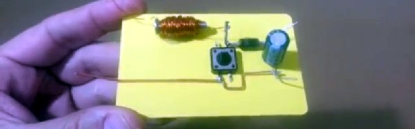
The circuit in question is probably as simple as it gets when it comes to a boost converter, and is not really a practical design. However it helps visualize what is going on, and exactly how a boost converter works, using just a few parts, a screw, enameled wire, diode, capacitor and a push button installed on a board.
The video goes on to show us the science behind a boost converter, starting with adding a battery from which the inductor stores a charge in the form of an electromagnetic field. When the button is released, the magnetic field collapses, and this causes a voltage in the circuit which is then fed through a diode and charges the capacitor a little bit. If you toggle the switch fast enough the capacitor will continue to charge, and its voltage will start to rise. This then creates a larger voltage on the output than the input voltage, depending on the value of the inductor. If you were to use this design in a real life application, of course you would use a transistor to do the switching rather than a push button, it’s so much faster and you won’t get a sore finger.
This is very basic stuff, but the video gives us a great explanation of what is happening in the circuit and why. If you liked this article, we’re sure you’ll love Hackaday’s own [Jenny List] explain everything you need to know about inductors.
(updated thanks to [Unferium] – I made a mistake about the magnetic field collapsing when the button is pressed , When in reality it’s when the button is released that this happens. Apologies for confusion.)