Every once in a while a project comes along with that magical power to consume your time and attention for many months. When you finally complete it, you feel sorry that you don’t have to do anything more.
What is so special about this Bingo ball reader? It may seem like an ordinary OCR project at first glance; a camera captures the image and OCR software recognizes the number. Simple as that. And it works without problems, like every simple gadget should.
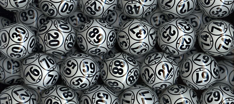
But then again, maybe it’s not that simple. Numbers are scattered all over the ball, so they have to be located first, and the best candidate for reading must be selected. Then, numbers are painted onto a sphere rather than a flat surface, sometimes making them deformed to the point where their shape has to be recovered first. Also, the angle of reading is not fixed but somewhere on a 360° scale. And then we have the glare problem to boot, as Bingo balls are so shiny that every light source reflects as a saturated bright spot.
So, is that all of it? Well, almost. The task is supposed to be performed by an embedded microcontroller, with limited speed and memory, yet the recognition process for one ball has to be fast — 500 ms at worst. But that’s just one part of the process. The project includes the pipelined mechanism which accepts the ball, transports it to be scanned by the OCR and then shot by the public broadcast camera before it gets dumped. And finally, if the reading was not reliable enough, the ball has to be subtly rotated so that the numbers would be repositioned for another reading attempt.
Despite these challenges I did manage to build this system. It’s fast and reliable, and I discovered some very interesting tricks along the way. Take a look at the quick demo video below to get a feel for the speed, and what the system “sees”. Then join me after the break to dive into the details of this interesting embedded build.
Initially, I thought I would have to employ a neural network for the recognition process, but it turned out the recognition is actually the simplest part of the project, and that it would be much easier and faster to do it algorithmically. The tough part is determining what’s what on the whole image, locating the best number, the line under it, and measuring how much it should be rotated. Starting with nothing more than a bitmap image, the processor has to do a lot of math even before it can be sure if the number consists of one or two digits.
VGA During Development
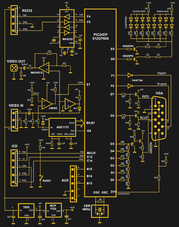
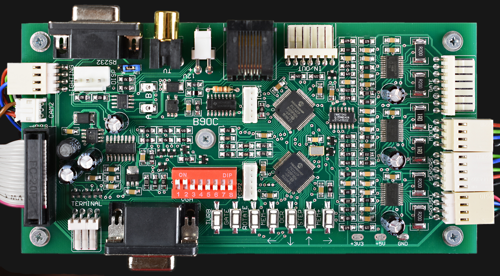
To make the development, maintenance and adjustments easier, the same MCU is used for VGA signal generation in addition to image fetching and processing. It doesn’t only display the scanned image, but also includes some current parameters and RAM contents. The controller board has a VGA connector, but it should not be used during the normal operation of the unit. VGA monitor has nothing in common with broadcast monitors in the Bingo hall, as there are two independent cameras and lighting systems.
VGA signal generation consumes a lot of processor time, so it is switched off during image fetch and processing, which is about 500 ms during each ball reading cycle. Sync signals are transparently generated by the internal PWM peripherals and they are active all the time, so that picture restore after RGB signal establishing is fast.
In this case, 16-bit microcontroller PIC24EP512GP806 was used, with 586/52 K of program/data memory and 60 MIPS execution speed.
Fetching the Image
The low-cost analog “cube” camera was used in the first phase of development, but was later substituted by a digital cube camera. Both were similar in price and performance, but the latter one came with the lens which has higher focal length, so the distance could be higher and the camera could see the larger area of the ball.
For such a small object, the best light source should be white LEDs, but the glare was quite bad with the shiny ball surface. I performed some experiments with diffusers, but with no luck. The eventual solution came from a quite different approach: very bright and sharp reflection, but with double exposure which uses different light sources. During the second image fetch process, the MCU selects the lower value for every pixel.
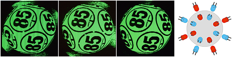
As the hotspots never match, they will be canceled and the resulting image (the third photo from the left) is evenly lit and glare-free. As an added bonus, the background light reflections were canceled in the process as well.
Please note that the system is embedded, without a screenshot function, so the images come from a VGA monitor being shot with a camera.
The light source is composed of 16 white LEDs, so that eight LEDs are active at a time. The image on the far right-hand side represents LED arrangement from the camera’s point of view. LEDs are colored red and blue here to help differentiate between groups for the first and second exposure.
This makes the process significantly slower, as now we have not only two exposures, but also the dummy frame time between two exposures, to allow the recovery and accomodation of the CMOS sensor after the lighting changes. That’s why the whole imaging process takes almost 100 ms.
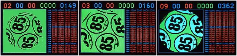
The resolution of the scanned image is 220×220 pixels, with 8-bit pixel depth. The analog grayscale image consists of only six bits, with the remaining two bits being used for blue and red color representation on the monitor, as the grayscale is actually greenscale. Those extra pixels are used as special flag pixels between processing steps, visible in the single step mode, as blue and red areas. This turned out to be very useful during program development and debugging.
The whole process is divided into 17 steps, which can also be executed in single-step mode for development and debugging purposes. The step number is displayed at the top left corner of the screen (see below), and the current state of the stopwatch with 1 ms resolution at the top right. This way it was easy to follow the execution time and optimize each step.
Ball Location and Stretching
To locate the ball precisely, X, Y coordinates for centroid (geometric center) are calculated, using formulas Cx = ∑CixAi / ∑Ai and Cy = ∑CiyAi / ∑Ai, where Cx, Cy are X, Y coordinates and A is the value of every pixel. As the background is predominantly black before this step, Cx, Cy will be approximately in the center of the ball. Then the whole frame buffer is moved as a 2D block, so that centroid is at coordinates X=110, Y=110, which is at the center of the frame. The center is marked with 2×2 red pixels (bit 7) only for developer’s convenience, as the processing firmware in most cases ignores bits 6 and 7.
Next, the ball diameter is measured, calculating the average pixel value on the perimeter for different diameters. Then, the background (every pixel that’s outside the diameter) is set to “white” or, more specifically, green (value 0x3F), to ensure better isolation of black areas. The background will be set to white or black a few times more during processing, each time the selection of black (ink) or white (paper) areas is required.
Flawlessly transforming a sphere to a flat surface is impossible, but the shape can be improved if the image is non-linearly deformed, like on the step 3 image. Small 16-bit microcontrollers don’t have an arithmetic coprocessor, and using standard trigonometric libraries would consume too much processor time. That’s why trigonometric lookup tables were used, and you can see on the stopwatch (top right blue digits) that, in this case, the execution time for the stretching procedure was only 11 ms. You can also see that the central part of the ball is mostly unchanged, and the edges are non-linearly stretched so that spherical deformations are minimized.
In step 4, similarly to the Unsharp Mask function in Photoshop, a new, blurred image is created. As there is not enough RAM space for another full frame buffer, it is performed on the auxiliary image which is scaled down to the resolution 44×44. The function of the unsharp mask is very important, as it ensures better selecting of “ink” pixels relative to “paper” pixels. Selecting means “setting of bit 7”, which will result in red areas on the VGA screen.
Now there are two images in the same frame buffer, the grayscale one (bits 0-5) and the binary one (bit 7). The latter is used in the preprocessing step 6, where small holes and scratches are eliminated. The selected image is first expanded and contracted, and then the process is repeated with the order of operations reversed — which results in the edges being smoothly rounded and garbage-free.
Component Manipulation
After a couple more preprocessing steps, more serious operations take place. The first one is known as “connected components”, where the isolated areas are selected and parameters for each one are acquired. This includes X and Y dimensions, X and Y center coordinates, number of pixels selected, and the Euclid’s distance from the center of the frame. This will help sort every component as a digit, the big circle, the underline or background. At this stage, it also becomes clear if the number contains one or two digits.
This step takes a lot of processing time, about 200 ms. Another problem was that the standard algorithm for connected components requires an auxiliary frame buffer of the same size, so I had to create a new algorithm which utilizes the same frame buffer, plus a small table for temporary coordinates.
At this point it is easy for the processor to choose the best candidate for recognition — it is the circle with the smallest Euclid’s distance from the center of the ball. Connected components inside this circle are taken into account, and everything else is expunged.
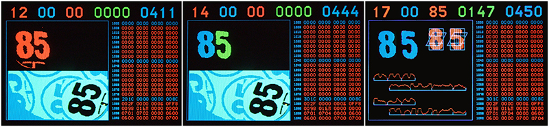
The balls in question are special OCR balls with underlined numbers, so that the angle of rotation can be measured. Now that the center of the circle is known, the program rotates the virtual “T” form, which corresponds to the underline shape, in 512 steps around the 360° circle, counting how many “ink” pixels it contains. The highest rated count dictates the angle of rotation, then the 2D block of the frame buffer is moved to the bottom right corner of the image (step 12 on the leftmost image), and the rotation is performed, moving the bitmap to the opposite corner of the frame buffer. Thanks to logarithmic lookup tables, this group of operations takes only 50 ms.
It keeps getting better with every step. Digits are selected with different colours, then one digit is moved to the safe distance, and then each digit is scaled to the known resolution of 30×46.
Recognition
As this reader was my first OCR project, I naively thought the recognition process would be the toughest part to solve. After each step was fully debugged and checked one by one, I reached the 17th and final step. As I already pointed out, my initial plan was to go for a neural network, but then I tried a simple algorithm and played around with it. I tested it with a few balls and you can’t imagine how shocked I was when I saw it works perfectly! At last the bitmap was properly rendered to two ASCII numbers.
The algorithm is quite simple. The bitmap for each digit was virtually divided in three parts, first horizontally, and then vertically. Then active pixels were counted at every column or row, and histograms created. There is also an added 7th histogram, which is slanted to help better detection of the crosscut lines at digits 4 and 7.
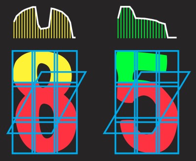 It took only 3 ms to build seven histograms for each digit and to compare them with prerecorded tables, calculate the sum of mean squared errors and sort the results. To make the development and debugging easier, all histograms are plotted to the screen.
After the results of the comparison are sorted, we get the winner for each digit (in this case 8 and 5), but our job isn’t done until one more thing takes place. The quality of reading has to be rated, so that the controller can estimate if the result is reliable enough.
If the number on the ball has only one digit, the table of errors for each digit (0…9) is sorted and the “winner” is compared with the second one (nearly-the-winner). If the ratio is high, that means that the recognition is successful. In our case it was 147%, which means that the second rated candidate has 147% more errors than the best one. For instance, the first one had 100 “error units” and the second one had 247. This is a good rating, although most ratings are north of 300%. Generally, ratings higher than 80% should be considered safe enough.
But what if there are two digits? A chain is only as strong as its weakest link, so the program will ignore the more successfully recognized digit (the one with higher ratio) and use the weaker one to make the final decision on success.
The controller has two basic modes of operation. In the fast mode, there is only one reading, which gets repeated (after the ball rotation) only if the first reading wasn’t rated well enough. In the slower (“safe”) mode, there are two readings whose results must match.
The reader was tested in Belgrade, in Eleks-M company, which produces casino equipment. The test was performed with one extra still camera which automatically recorded every ball reading, then the images (with filenames which contained nothing but the recognized ball number) were sorted alphabetically and the final check was performed manually.
The entire test lasted for 240 hours, which would help stress-test the durability of the Bingo blower in addition to the reader. After 10 days and 115,000 balls read, there was only one erroneous reading (ball 37 was read as 7), with the reader being set to fast mode. Testing in safe mode would be meaningless, as an error would probably never occur.
Mechanical Concept
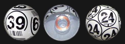 The physical path for Bingo balls is circular, with a stepper motor rotating the carousel by 90° for each ball cycle. There are four pipelined steps: ball in, OCR reading, broadcast recording, and ball out. Bingo blowers have followed the same functional pattern for decades. In the past, the balls were human-read (probably from the broadcast camera), then we got the Bar-code (left), then RFID reader (middle) and, finally, optical character recognition (right).
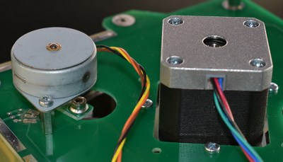 There is another stepper motor which rotates the ball under the OCR camera after scanning, to make it ready if another reading is required. The controller contains two equal MCUs: one scans the image, recognizes the number, controls LED lighting and generates VGA signal, and the other one drives stepper motors, communicates with the server and controls all parts of the blower.
The enclosure and mechanical parts are made of FR4, using the process described in my previous guide. The only exception is the carousel, which is made of laser cut acrylic. The main stepper motor rotates the carousel directly, and four magnets with one Hall sensor are responsible for home positioning.
If the controller decides that another reading is necessary, the small stepper motor rotates the ball slightly, in order to reposition numbers. The controller can also control the third stepper motor, which is used inside the blower unit, to open the entrance gate at the beginning of the game.
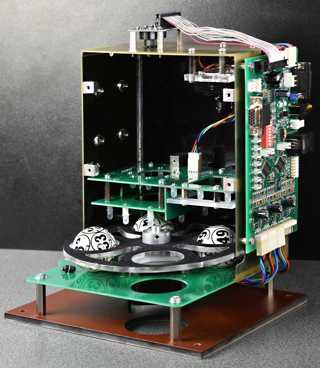
To make the unit more compact, the controller board is attached to the enclosure, so the only external cables are 12 VDC supply and RS232, for communication with the server. For very long distances, there’s a galvanically isolated current loop. There is also a USB version of the controller, but the limited length of the cable makes it hard to implement in some cases.
Two older versions of the project are described at
- https://hackaday.io/project/5649-ocr-for-bingo-balls
- https://hackaday.io/project/11515-optical-bingo-ball-reader-assembly.
At last, the firmware (for OCR microcontroller only) took nearly 80 K bytes of lookup tables and about 6,000 lines of assembly language code, excluding comments. You heard well — it’s all assembly language. I’m a hardware guy and I like to keep everything under my control.
I forgot to add one more thing, but you probably guessed it by now: doing projects like these is a blast.


Wow ! That’s a nice collection of tricks !
Congrats and thanks Voja :-)
“There is also a USB version of the controller, but the limited length of the cable makes it hard to implement in some cases.”
Active or fiber optic USB extender can fix that.
Nice polished build.
Great work and a well put read, but I’d have probably just modified the balls by drilling / embedding a small NFC chip / plugging each
Yes, but for the game fairness, you have to be able to prove that the balls are identical and centrally symmetric. Any modification casts doubt on mechanical uniformity of the system. Bar code was a simple but unsightly solution. This one is a perfect fit.
This solution is mentioned in the article near the end.
After a while the balls become nearly unreadable because of dirt, smudges, oil from fingers, cigarette smoke…
This hardware is a product sold to casinos. I think they keep up on replacing the balls as they wear.
I was hoping this was about dynamical systems and lottery drawings.. This system still has failure rate though..
And if it fails in the players favor, the casinos refuse to pay.
no casino uses ball drawings.. The closest thing is roulette spins and craps and sometimes at big casinos those little experimental low-rate games..
Most people don’t know there is a optimal strategy for everything it just typicall has a high cost. State lotteries you can buy up most of the combinations on rollovers etc..
There is probably even a dynamic system that can put odds on balls using print-weight, CFM, barrel space etc..
The odds are still going to have fail-rate though..
You’d think this would have been done years ago! And on a microcontroller! Wow!
Reminds me of the Dice-O-Matic
https://www.youtube.com/watch?v=7n8LNxGbZbs
Amazing and fast machine!
There’s another dice reader for SicBo game, I’ve built it about 10 years ago
https://www.youtube.com/watch?v=IFFpmOvcxSM
That’s a very low bandwidth random generator… but the bass is great ;-)
I’ve always wondered how hardware random number generators works… Thanks!
I don’t know if you are joking or not, but recent H/W RNG’s would be based mostly be based on quantum effects.
https://en.wikipedia.org/wiki/Hardware_random_number_generator#Quantum_random_properties
e.g. nuclear decay, – https://www.fourmilab.ch/hotbits/how3.html
As always, the devil is in the details! What a great explanation and walk through of the issues that needed solving. I learned a lot from reading this.
Impressive. Very impressive!
The project is greaaaaat but, 80 Kilobytes of lookup table!!!!!!!! Its really amazing how you were able to pull this off on your own. Sounds almost impossible to me.
“The eventual solution came from a quite different approach: very bright and sharp reflection, but with double exposure which uses different light sources. During the second image fetch process, the MCU selects the lower value for every pixel.”
Such a simple yet effective solution, very cool!
Did u try a polarizing filter to remove glare?
Nice technique on the double exposure
No, but I don’t think that it would be of any use here. Polarizing filters are good for glare elimination only if the angle of reflection is low, and if the polarization direction is uniform, which is not the case with spherical mirror.
That procedure could have uses in photography. Put two electronic flashes on a camera, at opposite ends. Flash and take 2 pictures in very rapid sequence then merge the two with processing for glare removal.
Sure, but correct me if I am wrong (I have some but not comprehensive image analysis background) that assumes you have enough CPU horsepower available to do real time image analysis in a timescale of milliseconds. There are embedded devices that are starting to become available commercially now that have that degree of horsepower under the hood but I don’t get the impression that this specific hardware does.
Processing wouldn’t have to be done super fast, just taking the images rapidly. Processing could be shunted off to a separate RAM and processing component to free the image recording system for another shot.
No, this would also work if you have a filter for both the surface and the camera. True, the effect is much less pronounced, but still. I use it all the time for OCR on shiny foils and such, and those are definately not flat and the angle of reflection is all over the place. The important thing is to also add a polarizing filter in front of the lightsource.
A dome light would’ve effectively eliminated this problem as well, the same goes for a coaxial light. Industrial applications don’t like double flashes, as objects tend to move. For this case, eh, speed is not an issue.
What works well is to put a polarizing filter over the light source and a canceling one over the camera lens. Specular reflection retains polarization and non-specular tends to create random polarization. In the case of photographing glass at 90 degrees, almost total extinction of the flash is possible, allowing images to be made of items in display cases.
Excellent write-up. This was a blast to read!
Insane. Both in the sense of “amazing work” and also “you must be mad to write all that in assembly”.
+1 great article
Very satisfying. Great work!
if it uses a “special OCR ball” anyway, why not print QR codes on them (interspersed with Arabic numbers for human reading)? QR codes can be read with cheap, commodity readers from a wide range of orientations.
I guess that the main reason is the same as for bar-code. If there are too small details which can affect reading, the system is sensitive to dirt and scratching.
Also, the cheap QR code readers dont like spherical distortions at all. Perspective is ok, spherical not so much,
Very nicely done.
Interesting project, would you let me know which camera did you use? Thanks!
Hi, so I’m wondering if anyone can help me out. I’m poking to invest in creating a similar tool but a tad different. So basically I want to be able to read a number that’s generated and then find it on a bingo card and have a phone tapper find that number on the card and click it. All within 2 secs. Is it possible?