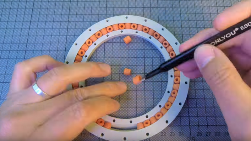
Consider the humble ball bearing. Ubiquitous, useful, and presently annoying teachers the world over in the form of fidget spinners. One thing ball bearings aren’t is easily 3D printed. It’s hard to print a good sphere, but that doesn’t mean you can’t print your own slew bearings for fun and profit.
As [Christoph Laimer] explains, slew bearings consist of a series of cylindrical rollers alternately arranged at 90° angles around an inner and outer race, and are therefore more approachable to 3D printing. Slew bearings often find application in large, slowly rotating applications like crane platforms or the bearings between a wind turbine nacelle and tower. In the video below, [Christoph] walks us through his parametric design in Fusion 360; for those of us not well-versed in the app, it looks a little like magic. Thankfully he has provided both the CAD files and a selection of STLs for different size bearings.
[Christoph] is no stranger to complex 3D-printable designs, like his recent brushless DC motor or an older clock build. The clock is cool, but the bearings and motors really get us — we’ll need such designs to get to self-replicating machines.


Really nice. Thanks for your video.
Here’s a good explanation of this type of bearing:
http://www.ina.de/content.ina.de/en/products_services/rotativ_products/crossed_roller_bearings/crossed_roller_bearings.jsp
That is such amazing work and a really good video! Hats off!
I’ve been waiting 40 years for something that finally got answered in the video. When I was working on large positionable antenna systems, the ones I worked on used ball bearings, but people I worked with described this type of bearing being used on even larger antenna positioners. I couldn’t figure out how the geometry could possibly work, thinking that the rollers would have to be tapered, but they told me that no, the bearings were completely cylindrical – they were reversible and there was no “top” and “bottom” to them. I was perplexed, because to me it couldn’t possibly work that way. But I put that aside, figuring it was either beyond my comprehension, or these other guys were mis-remembering something. So when I saw the picture, I thought, “aha!”, this guy will know if the rollers need to be tapered! So I watched the video, and again I was shown this type of bearing working with cylindrical rollers, and figured, well, I just must not have a proper geometrical model of it in my head. UNTIL 15:54 in the video, where [Christoph] describes problems he had when he tried a version with only 8 rollers: “cylindrical rollers are a good approximation for slew bearings with a lot of rollers; for bearings with a small number of rollers, they need to be cone-shaped.”
Vindicated at last!!!
Also, looking at the document posted above it looks like spacers in between the rollers are pretty common, which probably makes cylinders more practical.
Wizardry!
Possible to use pony beads?
Oo, now there’s an idea – I don’t have a 3d printer but quite liked to see how effective they might be but I do have a table-top cnc machine. So, maybe I could make the rings with a suitable 90deg bit on some plastic and use some aluminium tubing (which I have) to cut down for the bearings.
might try this on my CNC router too.
Definitely yes. I desiged my axial bearing in OpenSCAD and used 5mm pony beads. Works nice and smoooth
I really wish he evaluated the performance of the bearings. Even a ballpark check of run-out with an indicator would have been good, deflection under load would be useful to know as well.
Depending on performance this could either be game changing or useless.
I printed his shared model. My rollers came out at about 8.4mm diameter. I ended up not needing 2 rollers.
The problem with this design is there is no margin for error. Too small and there is play. Too large and it seizes or the two halves don’t fit. I would have thought a pair of large diameter angular contact bearings would be more forgiving for 3d printing.
I think this is manageable. As long as all of your rollers are the same size, you can print them slightly oversize and shim between the upper and lower halves to make the space for them.
It’s a pretty impressive build (although in my inexpert opinion, his brushless DC motor is even more impressive), but hey, it’s still a plastic bearing, so I’m not sure what it’s good for, except as an impressive build.
One could have small opening in the outer ring to allow adjusting the tension. It could be held together by thread/wire running in a grove. Alternatively one could print a semi-flexible band in Ninjaflex/Armadillo or similar. Disadvantage is that one cannot control outer diameter precisely, but I think that printed bearings are most interesting when integrated directly into a design – not as standalone/standardized parts.
With this solves the biggest issue with 3d scanners, The massive bearing used to support the turntable ( adault fidget spinner :P )
I’ve run out of excuses for that 3D Printed Lazy Susan project I’ve always dreamed about…
A bearing for that Star Trek TOS Captain’s chair replica!
Nice thing with cylindrical rollers if design tolerates lack of chamfers is that any tubing can be used as rollers. PTFE tubing from bowden tube?
Nice job! :)
We were discussing this at the office, Kodiak Bearings http://www.kodiakbearings.com. Would be cool to 3-D print hard to find bearings!