Retrotechtacular: Ford Model T Wheels, Start To Finish

There’s no doubt that you’ll instantly recognize clips from the video below, as they’ve been used over and over for more than 100 years to illustrate the development of the assembly line. But those brief clips never told the whole story about just how much effort Ford was forced to put into manufacturing just one component of their iconic Model T: the wheels.

An in-house production of Ford Motors, this film isn’t dated, at least not obviously. And with the production of Model T cars using wooden spoked artillery-style wheels stretching from 1908 to 1925, it’s not easy to guess when the film was made. But judging by the clothing styles of the many hundreds of men and boys working in the River Rouge wheel shop, we’d venture a guess at 1920 or so.

Production of the wooden wheels began with turning club-shaped spokes from wooden blanks — ash, at a guess — and drying them in a kiln for more than three weeks. While they’re cooking, a different line steam-bends hickory into two semicircular felloes that will form the wheel’s rim. The number of different steps needed to shape the fourteen pieces of wood needed for each wheel is astonishing. Aside from the initial shaping, the spokes need to be mitered on the hub end to fit snugly together and have a tenon machined on the rim end. The felloes undergo multiple steps of drilling, trimming, and chamfering before they’re ready to receive the spokes.

The first steel component is a tire, which rolls down out of a furnace that heats and expands it before the wooden wheel is pressed into it. More holes are drilled and more steel is added; plates to reinforce the hub, nuts and bolts to hold everything together, and brake drums for the rear wheels. The hubs also had bearing races built right into them, which were filled with steel balls right on the line. How these unsealed bearings were protected during later sanding and grinding operations, not to mention the final painting step, which required a bath in asphalt paint and spinning the wheel to fling off the excess, is a mystery.

Welded steel spoked wheels replaced their wooden counterparts in the last two model years for the T, even though other car manufacturers had already started using more easily mass-produced stamped steel disc wheels in the mid-1920s. Given the massive infrastructure that the world’s largest car manufacturer at the time devoted to spoked wheel production, it’s easy to see why. But Ford eventually saw the light and moved away from spoked wheels for most cars. We can’t help but wonder what became of the army of workers, but it probably wasn’t good. So turn the wheels of progress.

Continue reading “Retrotechtacular: Ford Model T Wheels, Start To Finish”

A business-card-sized fidget spinner with the Hackaday logo.

2024 Business Card Challenge: POV Fidget Keeps Your Info In Their Hands

So what if we’re halfway through 2024? People who needed to fidget all along still need something to do with their hands. So why not hand them a solution with your information on it?

Not only will this spin nicely, the spinning action will use magnets to energize PCB coils and light up LEDs for some persistence of vision action. Designing the PCB was easier than you might imagine thanks to KiMotor, a KiCad plugin to automate the design of parametric PCB motors.

Mechanical testing went pretty well with the bearings and magnets that [mulcmu] had on hand, along with a scrap PCB as the sacrifice. Although a bit difficult to hold, it spins okay with just the bearing and the shaft. Once the boards arrived, it was time to test the electrical side. So far, things are not looking good — [mulcmu] is only getting a few tens of mV out of the rectifier — but they aren’t giving up hope yet. We can’t wait to see this one in action!

Hurry! This is the last weekend to enter the 2024 Business Card Challenge! Technically you have until Tuesday, July 2nd, but you know what we mean. Show us what you’ve got!

Adding Two Axes Makes CNC Router More Than The Sum Of Its Parts

The problem with building automated systems is that it’s hard to look at any problem and not see it in terms of possible automation solutions. Come to think of it, that’s probably less of a bug and more of a feature, but it’s easy to go overboard and automate all the things, which quickly becomes counterproductive in terms of time and money.

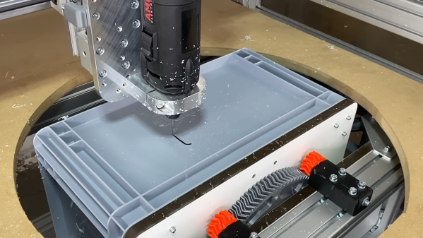
If you’re clever, though, a tactical automation solution can increase your process efficiency without breaking the budget. That’s where [Christopher Helmke] seems to have landed with this two-axis add-on fixture for his CNC router. The rig is designed to solve the problem of the manual modification needed to turn off-the-shelf plastic crates into enclosures for his line of modular automation components, aspects of which we’ve featured before. The crates need holes drilled in them and cutouts created in their sides for displays and controls. It’s a job [Christopher] tackled before with a drill and a jigsaw, with predictable results.

To automate the job without going overboard, [Christopher] came up with a tilting turntable that fits under the bed of the CNC router and sticks through a hole in the spoil board. The turntable is a large, 3D printed herringbone gear driven by a stepper and pinion gear. A cheap bearing keeps costs down, while a quartet of planetary gears constrain the otherwise wobbly platform. The turntable also swivels 90 degrees on a herringbone sector gear; together, the setup adds pitch and roll axes to the machine that allow the spindle access to all five sides of the crates.

Was it worth the effort? Judging by the results in the video below, we’d say so, especially given the number of workpieces that [Christopher] has to process. Add in the budget-conscious construction that doesn’t sacrifice precision too much, and this one seems like a real automation win.

Continue reading “Adding Two Axes Makes CNC Router More Than The Sum Of Its Parts”

What’s In A Slip Ring?

We know that when [Big Clive] puts up another video, the chances are we’re in for another fascinating look into a piece of tech on his bench. The latest is a slip ring assembly, and he gives it a teardown to reveal its secrets.

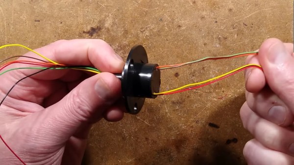
For most of us, the only place we encounter a slip ring is in some electric motors or alternators when it provides a connection via a conductive ring and a graphite brush from a fixed component to a rotating one. But they also appear as components in their own right wherever a rotating assembly needs an electrical contact, and it’s one of these that [Clive] has on his bench. It’s a compact unit with an impressive six conductors, and its manufacturer boldly claims that it’s good for mains voltages. We’re going with the verdict in the video below the break. That’s wishful thinking, given the size of the unit.

Inside is a rotor with six brass rings and a couple of decent little bearings, while the other half of the unit is a set of gold-plated spring contacts. There is extensive use of potting, and the verdict is that this is a surprisingly good quality component for the eBay price. We look forward to our community finding inventive uses for them. Having a ready-made unit sure beats making your own.

Continue reading “What’s In A Slip Ring?”

Kino Wheels Gives You A Hand Learning Camera Operation

Have you ever watched a movie or a video and really noticed the quality of the camera work? If you have, chances are the camera operator wasn’t very skilled, since the whole point of the job is to not be noticed. And getting to that point requires a lot of practice, especially since the handwheel controls for professional cameras can be a little tricky to master.

Getting the hang of camera controls is the idea behind [Cadrage]’s Kino Wheels open-source handwheels. The business end of Kino Wheels is a pair of DIN 950 140mm spoked handwheels — because of course there’s a DIN standard for handwheels. The handwheels are supported by sturdy pillow block bearings and attached to 600 pulse/rev rotary encoders, which are read by an Arduino Mega 2560. The handwheels are mounted orthogonal to each other in a suitable enclosure; the Pelican-style case shown in the build instructions seems like a perfect choice, but it really could be just about anything.

To use Kino Wheels, [Cadrage] offers a free camera simulator for Windows. Connected over USB, the wheels control the pan and tilt axes of a simulated camera in an animated scene. The operator-in-training uses the wheels to keep the scene composed properly while following the action. A little bit of the simulation is shown in the brief video below, along with some of the build details.

While getting camera practice is the point of the project, that’s not to say Kino Wheels couldn’t be retasked. With a little work, these could be used to actually control at least a couple of axes of a motion control rig, or maybe even to play Quake.

Continue reading “Kino Wheels Gives You A Hand Learning Camera Operation”

Feeling The Heat: Railway Defect Detection

On the technology spectrum, railroads would certainly seem to skew toward the brutally simplistic side of things. A couple of strips of steel, some wooden ties and gravel ballast to keep everything in place, some rolling stock with flanged wheels on fixed axles, and you’ve got the basics that have been moving freight and passengers since at least the 18th century.

But that basic simplicity belies the true complexity of a railway, where even just keep keeping the trains on the track can be a daunting task. The forces that a fully loaded train can exert on not only the tracks but on itself are hard to get your head around, and the potential for disaster is often only a failed component away. This became painfully evident with the recent Norfolk Southern derailment in East Palestine, Ohio, which resulted in a hazardous materials incident the likes of which no community is ready to deal with.

Given the forces involved, keeping trains on the straight and narrow is no mean feat, and railway designers have come up with a web of sensors and systems to help them with the task of keeping an eye on what’s going on with the rolling stock of a train. Let’s take a look at some of the interesting engineering behind these wayside defect detectors.

Continue reading “Feeling The Heat: Railway Defect Detection”

Icicle Patterns With Custom Gantry

[Cranktown City] uses a number of custom-built linear rails used as gantries for various tools in the shop. The first is on a plasma cutter, which is precise but difficult to set up or repair. Another is for mounting a camera, and while it is extremely durable, it’s not the most precise tool in the shop. Hoping to bridge the gap between these two, he’s building another gantry with a custom bearing system, and to test it he’ll be using it to create patterns in icicles hanging from an eave at his shop.

While this isn’t the final destination for this gantry, it is an excellent test of it, having to perform well for a long period of time in an extremely cold environment. The bearing system consists of a piece of square steel tubing turned 45° inside another larger square steel tube and held in place with two sets of three bearings with V-shaped notches. To drive the gantry he is using a motor with a belt drive, and for this test a piece of drip irrigation is mounted to it which lets out a predetermined amount of water on top of the roof to create numerous icicles beneath with various programmed lengths.

After a few test runs the gantry system can create some icicles, although they don’t have the exact sine wave shape that [Cranktown City] programmed into it. They are varying lengths though, and with no more cold days in the forecast he’s called it a success. This isn’t the final destination for this robotic linear gantry, though, but it did help him work out some of the kinks with it beforehand. For other sources of inspiration, take a look at this linear rail system also used for driving various robotic tooling.

Continue reading “Icicle Patterns With Custom Gantry”