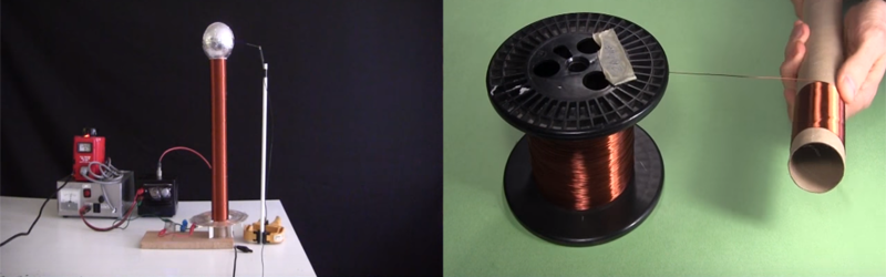
YouTuber [RimstarOrg], AKA Hackaday’s own [Steven Dufresne], shows how to make a DIY inductor for a specific inductance. This is obviously a great skill to learn as sometimes your design may call for a very accurate inductance that may be otherwise hard to find.
Making your own inductor may seem daunting. You will have to answer a few questions such as: “what type of core will I use?”, “how many turns does my coil need?”, or “how do I calculate these parameters to create the specific inductance I desire?”. [RimstarOrg] goes through all of this, and even has a handy inductance calculator on his website to make it easier for you. He also provides all the formulae needed to calculate the inductance in the video below.
Using a DIY AM Radio receiver, he demonstrates in a visual way how to tune an AM Radio with a wiper on his home-built coil. Changing the inductance with a wiper changes the frequency of the radio: this is a variable inductor,
This video is great for understanding the foundations of inductors. While you may just go to a supplier and buy yours, it’s always great to know how to build your own when you can’t find a supplier, or just can’t wait.


Good article.
Am I the only one wondering why it wasn’t written by [Steven Dufresne] instead?
Nope. I wondered the same! I snuck in and fixed it.
HAHA I never even realised apologies.
No worries, Jack. If you’re a Hackaday contributor then you wear multiple hats. Hard to keep track of them all.
Not bad, but it is a definitely a simplified design calculator. When using ferrous cores, the relative permeability of the core is non linearly dependent on the materials permeability and the length to diameter ratio of the core.
Also left out is the distributed capacitance of the windings which will dictate the resonant frequency of the coil. This in important because it limits the frequency range you can tune in.
Some crystal radios tune by sliding a ferrite core into the coil. I had a “rocket radio” as a kid that tuned by this method.
Now I’m wondering what would happen if assorted size ferrite / iron cores were added to a Tesla coil. Considering the voltages involved (and the fact I don’t have a Tesla coil ) I’ll leave that for others to answer.
My Tesla coil building experience is limited but I think that putting a ferrite/iron core in the secondary of a Tesla coil would have a negative effect, assuming you were thinking about the secondary. The coil has a high voltage across its length and the conductive content in the core would be shorting it out — or maybe not if the core is made of isolated conductive particles.
I’m no expert but every Tesla coil I’ve seen has an air coil as the secondary. Cheapo ones normally use PVC and it works great.
Your right about breakdown to the core being a problem if you used a ferrite core in a tesla coil. However, there are other reasons you wouldn’t want it as well. For one thing you don’t want too much coupling between the primary and secondary coil as this will affect the Q of the secondary and it’s the high Q of the secondary that makes it resonate and produce high voltage. Tesla coils are RF transformers and thus a bit different from regular transformers. The secondary, it’s stray capacitance and the top load form a resonant circuit and the resonant frequency of that circuit is the RF frequency the coil runs at.
That’s a very basic calculator indeed. Inductors are notoriously hard to get right.
This is the only calculator I know of, which gives results more accurate than the measurements you put into it:
http://hamwaves.com/antennas/inductance.html
It includes skin effect, proximity effect and self resonance! The derivation is explained on the rest of the page, if you’re into that sort of thing.