The electrical grid transmits power over wires to our houses, and our Bryan Cockfield has covered it very well in his Electrical Grid Demystified series, but what part does the earth ground play? It’s commonly known to be used for safety, but did you know that in some cases it’s also used for power transmission?
Typical House Grounding System
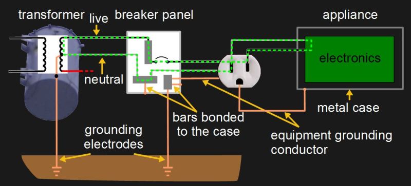
A pretty typical diagram for the grounding system for a house is shown here, along with a few of the current carrying conductors commonly called live and neutral. On the far left is the transformer outside the house and on the far right is an appliance that’s plugged in. In between them is a breaker panel and a wall socket of the style found in North America. The green dashed line shows the normal path for current to flow.
Notice the grounding electrodes for making an electrical connection with the earth ground. To use the US National Electrical Code (NEC) as an example, article 250.52 lists eight types of grounding electrodes. One very good type is an electrode encased in concrete since concrete continues to draw moisture from the ground and makes good physical contact due to its weight. Another is a grounding rod or pipe at least eight feet long and inserted deep enough into the ground. By deep enough, we mean to include factors such as the fact that the frost line doesn’t count as a good ground since it has a high resistance. You have to be careful of using metal water pipes that seemingly go into the ground, as sections of these are often replaced with non-metallic pipes during regular maintenance.
Notice also in the diagram that there are places where the various metal cases are connected to the grounding system. This is called bonding.
Now, how does all this system grounding help us? Let’s start with handling a fault.
Handling A Fault
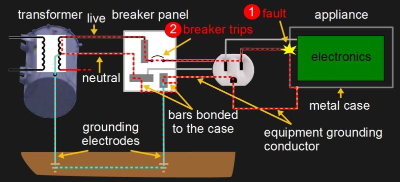
One purpose of the grounding system is to cause a breaker in the breaker panel to trip if there’s a short circuit somewhere. That happens if there’s an appliance with a metal case and the insulation on the live wire in the appliance is damaged, causing the copper wire inside to touch the metal case. The case becomes an extension of that live wire. This is called a fault.
But the metal case is connected to an electrical path consisting of the ground wire in the power cord plugged into the wall socket, as well as the wire from the wall socket to the breaker panel. In the US National Electrical Code (NEC) these are referred to as the equipment grounding conductors.
In North America at least, in the box where the service first enters the house, the equipment grounding conductors are connected to the neutral wire. In this case that box is the main breaker panel. In most breaker panels this connection is made by having both the wires go to metal bars that are screwed, or bonded, to the panel’s case, thereby making the electrical connection through the case.
Following the red dashed line from the fault, a high current now runs through the live wire, through the appliance’s case, and uses the equipment grounding wires as the return path to the breaker panel. From there the current goes through the panel’s case to the neutral bar and neutral wire back to the transformer. Along the way, the live wire runs through a breaker in the breaker panel and the current is high enough to trip that, opening the circuit and making it safe again.
But where does the earth ground come into it? Often it doesn’t. Sometimes, however, as shown by the blue dashed line, a little current will flow through a parallel path including the grounding electrodes and the earth ground.
Discharging Stray Charge
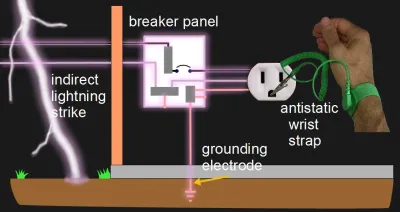
There’s a purpose for earth ground that many here on Hackaday are quite familiar with, and that’s stray charge and problems with electrostatic discharge to electrostatic-sensitive devices and components such as MOSFETs, CMOS ICs, and TTL chips. Methods for handling this are to wear an antistatic strap or to work on an antistatic mat. These usually have a clip or a dedicated socket for connecting to earth ground.
The charge on your body will put you at a different potential than the ground and so current will flow between you and ground. The earth ground is largely electrically neutral and will easily absorb the charge, leaving the combination of the ground and you neutral.
Not all electrostatic discharge is accidental. We previously covered experiments by [Kevin Darrah] where he deliberately tested the effect of it on various components as well as tried out circuitry for protecting against it.
Metal cases can also become energized by indirect lightning strikes and any charge build-up will drain to earth ground in the same manner.
Single-Wire Earth Return (SWER)
To save on costs, mostly in rural areas or for remote, isolated dwellings, sometimes only a single wire is used for transmission. This eliminates the cost of the neutral return line, provided the cost savings makes up for the decrease in efficiency. The decrease in efficiency is due to the use of the higher resistance earth ground as the return path. This turns out to be quite safe and there are over 200,000 kilometers of transmission lines done this way in Australia and New Zealand. In the US, it’s used in portions of the Midwest and Alaska.
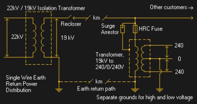
Power is first supplied by the grid to the primary of an isolation transformer, isolating the grid from the earth. Here, the voltage is typically stepped down from 22 kV to 19 kV. One side of the secondary is the single transmission wire and the other side goes to earth ground.
Distribution transformers are then used at customer sites where the 19 kV is converted to voltage suitable for the customer, 240 volts for example. One side of the primary is the single wire and the other side goes to earth ground for the return, which eventually makes its way back to the earth ground side of the isolation transformer.
Soil resistance is an issue. Dry soil is less conductive than wet, and in Alaska the ground rods have to extend to below the permafrost, as the ice is also less conductive. In addition, this higher resistance also causes the primary’s voltage to float higher and make it difficult for self-resetting breakers to reset, as they rely on a potential difference.
Additional phases can be added by adding second and third transmission lines.
Grounding Out
Have you had experience trying to create a good earth ground? Perhaps you’ve encountered soil that was too dry, and had to work around it? Or, as happens all too often, you work in a place where you’re certain some wall sockets just don’t have ground connections at all. Let us know in the comments below.
Or step over to the live side of electrical distribution and check out Bryan’s Electrical Grid Demystified series.



I think what confuses some is seeing the neutral and the ground bonded in the circuit panel.
http://www.esgroundingsolutions.com/why-do-you-have-to-bond-the-neutral-and-the-ground-wire-in-the-main-panel/
Bonded ground is not always the case. Isolated ground is used in many systems where electrical noise is a problem, and in some cases uses the same home runs back to the box, but neglects to bond the neutral and ground bars, so that a direct earth ground can be made. Its mostly common with hospitals, not residencies or commercial construction, but its out there.
Isolated grounds are actually bonded to the neutral at some point in the system. It being isolated just means that it’s not connected directly to the typical grounds that are used. Examples of those typical grounds would be your metal conduit boxes, raceway, etc that everything else uses pretty readily. The isolated ground is a separate wire connected directly to the ground terminal of that device and goes back to a panel (not necessarily the panel that feeds that receptacle, may be upstream panel). The local hospital (one of the top 3 in the U.S.) I have never come across IG’s in 10 years of doing electrical design for them. Where I do see IG is in retail and restaurants typically built out by “design build” contractors that know little what IG is or is for, other than the POS computers supplier say they need those orange receptacles.
Imma gonna put on my electrician hat and pontificate! A thing folks sometimes miss in quick reads of the NEC and related documents is the difference between a “grounding” conductor and a “grounded” conductor. GroundED is the neutral – it leads to a point where the voltage between that and ground is zero (voltage at any point may not be zero because copper has resistance) and is expected to normally carry current (so if you cut it, there’ll likely be a substantial voltage difference between the two ends). The groundING conductor is there to provide good connectivity to ground for bonded things so that if your energized refrigerator fault scenario above happens, there’s a better path to ground than via some random person who just wants to get a beer and turn on the water tap at the same time so they’re holding a grounded faucet when they touch the now-120v-charged fridge frame. Better to blow a fuse right away than fry an unsuspecting person later.
True story: I once ended up working on a job where I was replacing an electric service at a house where the line from the street came in underground in an old metal pipe. I got unexpectedly shocked a few times as I was poking at things, was very confused, and then poked around with my voltage testers and figured out that the actual pipe carrying the wires in from the street was live. The local gas company had been digging nearby and their equipment cracked the electric service pipe such that it nicked the wires. The pipe itself was so corroded that there wasn’t good connectivity between the pipe exterior and the ground, so it didn’t cause a huge short circuit detectable from upstream, but the freshly broken edge made fine connectivity with the nicked wire.
Current flow via the earth is also why we run into problems with geomagnetically induced currents – it turns into an unintentional single wire transmission scenario that can create a (mostly) DC voltage offset that can push transformers out of safe operating zones and totally mess things up.
QUOTE: “the difference between a “grounding” conductor and a “grounded” conductor.” That IS a gotcha for many people. I have had electrical inspectors, knowing I was an Engineer but not a licensed Electrician, ask me “Where is the GROUNDING CONDUCTOR? Show me the GROUNDED CONDUCTOR”. I would make a point of showing them the point in the service entrance where the GROUNDING CONDUCTOR (from the ground rod) was bonded to the GROUNDED CONDUCTOR (The Neutral connection bar). Then they were usually, “OK, good, now this looks like suspiciously neat wiring, like it was done by the home owner :-) “
holy shit, you’ve restored a little of my faith in your field. Most ive met know the code but when it ccomes to why its that way they are clueless. I’ve gotten into an argument with one about standard 120 or 220v mig welders being low voltage high amperage devices. he swore up and down he could turn the weld voltage up to over 100v. when i asked how come he could weld putting his hand on the piece and was here to talk about it he said you cant touch it. i forget the specifics of the other point that scared me but it involved long wire runs and he demoed a lack of underfstanding of i^2*r.
Don’t you have differential fuses in USA? In Europe in newer installations I think this is standard. Differential fuse turns off when hot (here: live) and neutral wires current differs and this difference can be much smaller than for example 16 amps or what main fuse do you have. Thanks to this it can work even on small leaks between live wire and ground, for example through human body or moisture.
Ground fault circuit interruptors are pretty common in the US – generally built into the receptacle and able to protect that plug and anything downstream fed from the “load” terminals on the GFCI. I want to say it trips if there’s something like 4 microamps differential but I’m much too lazy to google it so I might be totally off. GFCI receptacles are required in damp areas, including kitchen counters, bathrooms, and exterior areas, and have also been used to make legacy ungrounded outlets safer. The past 15 or 20 years have seen the rise of AFCI in the US, arc-fault circuit interruptors, which look for arc faults rather than ground faults. They’re required in bedrooms in dwellings and other similar locations, and so folks will sometimes just retrofit an existing circuit with an afci-capable breaker. In most circumstances, making a change to existing electrical wiring doesn’t require making changes to the existing circuitry to bring it into compliance with current NEC standards, but this does not apply to requirements to install AFCI, so if you touch it for pretty much anything, you need to add AFCI protection to the circuit if it’s required in new construction.
(None of those would apply in the case I was talking about, where there were no breakers between the bare wire ends sticking out of the pipe in the basement and some big-ass transformer upstream)
Ok, so I understand why it is not on above schematics. In Europe GFCI is typically mounted together with overload fuses
That is sometimes done in the USA as well, but is more expensive than installing a GFCI at the first receptacle in the circuit.
Yep My mobile home from the 80’s has GFCI breakers in the panel, but also has outlets that are GFCI in the garage as it was a later addition.
And it’s so nice to be able to test and reset from the source rather than having to trek out to the panel.
I grew up in an older home with two-wire wiring in the older part. I got into computers and all that stuff comes with 3 prong cords. For that, GFI outlets are a good workaround, as (if I am not mistaken) a GFI outlet is actually allowed to have its ground pin disconnected in this particular circumstance (when no ground wire is available). This is obviously a huge no-no on any other outlet, but the GFI makes up for the lack of grounding, at least from an electrical safety perspective (in principle).
When a handyman that was part of the extended family remodeled my mom’s bathroom he got on his high horse and was incredulous about when the addition that addition was wired initially the bathroom did have GFCI protection. My mom asked me about it, I advised her it was protected, and to tell the”expert” the protection was mounted in the service panel. Turned out the expert was ignorant of they ever existed as pane mounted devices. I wired the addition shortly after the GFCI where required by the NEC, and yes they where very pricey. Te device has been in place for decade without failure. Inexpensive receptacle locate devices I have used in later work tend to fail often To point I have to wonder if the more expensive panel located devices may be worth the money.
Breakers with built in GFI’s are a royal pain in the ass. About the only thing more frustrating than a GFI breaker is an outlet that is daisy chained off of a GFI outlet. This was common when GFI outlets first came out and were in the mid double digit’s a pop. You could have one in a room and daisy chain the other outlets off of it, them being protected by it. Of course the problem is that many people did not know that so they pop the GFI and than look for a popped breaker, and don’t find one… If they were lucky they would find the popped GFI before calling in for expensive help.
The GFI breakers are a real pain because if you do something stupid and pop the thing, it is more than just undoing the stupidity and pushing the reset button. It is more like you undo the stupidity and get to walk sopping wet, covered by a towel down in the far reaches of your basement to go poking around in the breaker box to reset the thing. If you don’t see how this would unfold, wait until someone in your household drops their hair dryer in the sink after taking a shower and it will make perfect sense.
What’s the use case for a hair dryer and a sink full of water? and who TF would do that, GFCI or not? I would dope-slap someone in my house who tried that.
@Fred …think Silvia plath but electrical
Some builiding codes are requiring house-level GFCI’s but interrupting too much power for a single fault can created dangers. A GFCI on a bathroom outlet is good. It’d keep someone in the tub from being killed by a defective smartphone charger. But its far better to trip just that outlet than to trip all the power in the house, leaving someone sitting in the tub in a dark room. That creates dangers of its own.
And as someone else noted, many GFCI’s installed at the beginning of the power flow can provide protection to all outlets further from the breaker panel that it. Put it on the first outlet in the kitchen, and all the others are protected.
GFCIs are dirt cheap. There’s really no reason anymore not to have every circuit on the house on an independent GFCI. You shouldn’t ever be in the dark because a GFCI tripped. … Rat chewing through the light fitting not withstanding of course. :-)
in the UK, a new consumer unit must a split load, i.e. have a minimum of 2 RCDs (GFIs), such that 100% of the consumer circuit cannot fail due to a nuisance current in one RCD.
I was going to write some stuff but changed my mind again.
Just don’t trust anything. test it your self and be safe.
I have been a electrician for over 30 years now. and have never trusted anyone or thing. And I still have gotten zapped.
Even God hates me sometimes.
One thing I will say.
I have done some really cool things. And gone places you would never have dreamed of.
Just be as safe as you can…
Grounding issues wreak havoc with sound equipment. I have had situations where over-grounding has caused issues where there is potential between ground rods, so my amplifiers at the back of the house and my direct boxes at the front of the house cause issues unless the ground is lifted between them.
I have also had to rewire houses a few times while overseas where a misunderstanding about grounding has created unsafe conditions, where simple items like “grounding” to a water pipe was insufficient, neutral and ground were not bonded, or ground rods were added to a floating grid.
My understanding is that breaking ground loops is the big reason the MIDI spec calls for current loop signaling.
Grounding to a water pipe is a very bad idea in some places.
The soil can corrode the pipes.
Or more critically, the pipes have been replaced with plastic somewhere out of sight.
Our 1910 house got a sudden water leak. Plumber traced it to a badly corroded service pipe out by the meter near the street. When he cut through the pipe he got a bad electric shock!
Turns out squirrels had chewed through the neutral up at the pole transformer, and the house had been grounded to the water pipe, so it became the neutral conductor. All the current flow corroded the pipe. Neutral fixed, service pipe replaced with plastic, all is well.
True story. Wife was in the shower. I was in the kitchen. I flipped on the light and she yelled!
She complained about getting shocked. Shocked I tell you. What followed was a grand investigation of voltages and actions. 110 volts from shower head to drain when the kitchen light was on, zero when it was off.
Took a bit of exploration but found two big things wrong with the wiring in this rental. One — the light fixture over the sink had the hotwire pinched to the case causing a short to ground. This was clear and obvious on visual inspection — easy fix. But why did that not blow a fuze before? Could it be that there was no ground?
The system was grounded to a water pipe. That water pipe was galvanized but looking a little deeper, it was connected to plastic. And that short length of galvanized was near the surface in very dry soil. A bona fide ground rod went in shortly.
All the above happened in the ’70s. But it’s not unheard of. KBR in Iraq did some shoddy work leading to the deaths of some 18 American servicemen. Damn near identical circumstances for which there really is no excuse.
http://www.nytimes.com/2009/01/23/washington/23electrocute.html
BTW, we still be married :)
In Afghanistan I often found wiring that was atrocious. We lived in modified steel shipping containers where the camp was powered by generators. Nothing was grounded and when there was water on the ground if you touched the outside of the shipping container (where your feet were on damp ground) you would get a nasty shock. I pulled out a multi-meter and found that shipping container to ground was at 115v! Luckily I got that fixed and not one got anything worse than a bad ‘bite’.
Another anecdote: I had a antenna disconnected from a radio with the coax cable hanging from the wall. We had a dust storm which generated so much static electricity that there were constant arcs jumping from the conductor to the barrel of the UHF connector, that’s why mil grade stuff has serious protection circuitry.
Man I didn’t think about the static from the sand storms. Good to know :) My BiL had some stories about container living over there and the electrical problems he faced but mainly ground loop stuff and brown out probs. That place is dangerous all over lol.
Another note on bonding neutral to ground.. Some have pointed out that isolated grounds are used in places such as hospitals. Another important place for grounds not to be bonded to neutral is in sub panels (i.e. garages, additions). In this case, the breaker panel will have 2 bars, one for neutral, and one for ground, and they should not be connected.
The reason for this is that if the neutral wire back to the main panel is damaged, the end result will be safe (no power to the sub panel) If the neutral and ground were bonded at the sub panel and the neutral connection cut, all the current would be carried on the ground wire and would likely not be detected.
that’s why the sub unit should have an RCD.
In the US, the ground and neutral (grounding and grounded conductors) should only be bonded near the service entrance. Anywhere inside of that, the neutral and ground should be separate. This helps keep things from getting too wacky with ground loops and potential unexpected voltage differentials.
That is also true in the UK and most parts of the world.
(I think the first paragraph should be more explicit about the fact it’s the method used in US and Canada and that other country can have very different way of managing grounding… Not everyone use TN-C-S system)
Fascinating article. Why the 22Kv to 19Kv step down? I am not being critical, I just don’t understand. It seems almost pointless other than providing isolation, but I am sure there is a big picture I am not seeing.
It’s actually a step-up! 22kV phase-to-phase is 12.7kV to neutral/ground.
19kV is the same voltage relative to ground as 33kV (phase-to-phase), a common transmission voltage.
So it was almost certainly done to allow them to use the same insulators, fuses, switches, etc as the 33kV systems.
The allowed SWER voltages (in Australia) are 11, 12.7, and 19kV.
[AS 2558-2006 Australian Standard™ Transformers for use on single-wire earth-return distribution systems]
edit: Oops, correction: it’s not a step up transformer, the primary is connected phase-to-phase.
I was working in Greece a few years ago and we had a box mounted on a transformer pole. It stopped working. Upon further investigation they had nicked the transformer. The box which must have easily been worth 20 times the scrap value of a transformer, was left neatly on the grass
A Navy buddy from the Philippines worked for a power company there. He told me about a copper thief they found out at the end of a several mile single tap. He started from the main lines, chopping the ground wire with a hatchet and yanking the copper wire down. At the end of the tap, with no ground wires, the neutral became a huge transformer. They found the guy dead next to a pile of coiled-up wire with the last cut ground wire in his hand.
I used to work with enormous analogue mixing desks (think 96 channel) for pro studios. As part of the customer acceptance tests the desk would be set up in a factory and the engineers would check that the noise was within spec. It turned out that good grounding was essential to getting good performance, so we had a length of welding cable leading to copper rods that were thrown in the creek out the back. But in summer the creek dried up so the ground got high resistance and the noise level increased so that the tests didn’t pass.
So on the way back from the pub everyone would piss on the ground rods. The acceptance engineers thought it was hilarious. And it was a great excuse for a lunchtime drink.
Realize that high voltage transformers are very dangerous. Even trained engineers setup systems wrong. Remember that you should try not to have removing one wire turn your project into a death trap. I have seen PE have a lineman wire a transformer phase to gnd in an ungrounded system. With one break in the ground wire you have line on one side through your transformer and gnd on the other side. Be safe and dont rush. Think though all the possible scenarios of wires becoming disconnected while keeping your system safe.
@ Annie Here in the USA the NEC requires the kitchen of even an one bedroom dwelling have 2 20 A. small appliance circuits, so kitchen circuit are or should be separate from other circuits, save perhaps, for the lighting in the kitchen.
With SWER system the Earth return is not analogous to the neutral on the secondary side of the service transformer. Mobile home leave the factory with the ground buss not bonded to the neutral buss. Because in the US there are still place that don’t employ a grounded neutral conductor. I the event a mobile come is connected to such a system the mobile home becomes ground point for every home it shares a transformer secondary with.
My family has grain bins and a corn dryer 3 phase 220 set up. Every few years they would have to replace the service boxes because one of the legs would rust away. I asked one of my electrician teachers and he suggested it was shorting to ground at some point. My family looked at me incredulously when I suggested it. (More of a downtime/cost issue.)
Yet, when my cousin had to redo the motor controllers he found that mice had chewed the wire in the gooseneck. The boxes and wires were so old and corroded that it didn’t pop the fuses.
Considering the mess the electrical is I am surprised no one got killed.
This can certainly cause problems!
In the post above “HANDLING A FAULT” what would happen on appliances of the customer if it occurs a short-circuit or fault between the utility transformer´s and breaker panel (upstream)?