When we first saw [Ajlitt’s] Hackaday.io project Terrible Cluster we thought, perhaps, he meant terrible in the sense of the third definition:
3. exciting terror, awe, or great fear; dreadful; awful. (Dictionary.com)
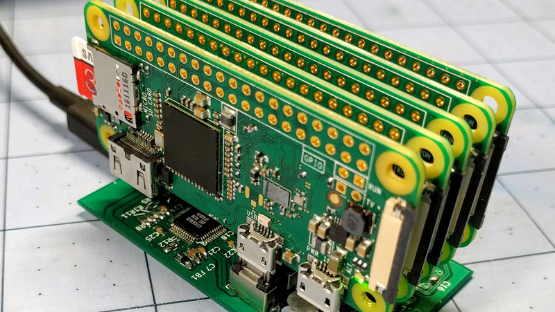
After looking at the subtitle, though, we realized he just meant terrible. The subtitle, by the way, is: 5 Raspberry PI Zeros. One custom USB hub. Endless disappointment.
There are four Raspberry Pi Zero boards that actually compute and one Raspberry Pi Zero W serves as a head node and network router. The total cost is about $100 and half of that is in SD cards. There’s a custom USB backplane and even a 3D-printed case.
At first, using five tiny computers in a cluster might not seem like a big deal. Benchmarking shows the cluster (with a little coaxing) could reach 1.281 GFLOPS, with an average draw of 4.962W. That isn’t going to win any world records. However, the educational possibilities of building a $100 cluster that fits in the palm of your hand is interesting. Besides, it is simply a cute build.
We’ve seen much larger Pi clusters, of course. You might be better off with some desktop CPUs, but — honestly — not much better.


This is such an excellent project. I love the sheer terribleness
“At first, using five tiny computers in a cluster might not seem like a big deal. Benchmarking shows the cluster (with a little coaxing) could reach 1.281 GFLOPS, with an average draw of 4.962W. That isn’t going to win any world records. ”
I could see this under the heading, 100 and 1 places one can hide a lot of computing power.
It’s only a matter of time before someone smuggles a Pi into a prison.
Smuggling in the Pi “through the usual channel” wasn’t too hard but they’re still struggling with the keyboard.
There are waterproof keyboards made of silicone rubber which can be rolled quite tightly. :-) But I don’t know adequate screens.
Mini projectors… (If you’re brave enough)
Except that the GPU on this SoC is not terrible, and can be used for things like DFT.
OpenMP is also not terrible…
Maybe try to calculate Pi on a Raspberry Pi 0 cluster ;)
That’s been one of my Long Term Goals That I’ll Probably Never Get Around To for this project. This project in particular is what got me thinking about serious GPGPU with the PI0: https://github.com/nineties/py-videocore
Also a good intro to OpenMP on the Pi:
http://www.softwarecoven.com/parallel-computing-in-embedded-mobile-devices/
Note too that the default gcc build flags use a “safe” subset of the ARM instruction set on the Raspberry Pi OS.
One can enable the advanced CPU media instructions for a specific program if your application has tolerant error bounds.
I have a hat that does the same, sat on an old B+. Learnt a lot about networking when trying to set it up myself without using the pre built images from the vendor. Is a good tool to learn with. :-)
This project has a sister in the cluster hat https://clusterhat.com/
ERR_SSL_PROTOCOL_ERROR is what I get…
Works for me, I’m in the UK.
Boy, did I read that title wrong!!
Oh. Yes. Well, at least the sentiment is the same.
I was going for the Merriam-Webster definition #1, “extremely bad”, specifically 1b “of very poor quality” or 1c “strongly repulsive”.
Try the first 30 seconds of this:
https://www.youtube.com/watch?v=hExE6iLxfEw
I dunno, during the HPL testing I was seeing die temps creep up to 75 degrees C in the innermost slots. If I can get the GPUs to keep busy then it could get terribly violent.
“the educational possibilities of building a $100 cluster that fits in the palm of your is interesting.”
I think you accidentally a word there :-)
===Jac
Perhaps he just misspelled “yore”?
At ~$10 the OrangePI zero could be a nicer contender for a project like this. It has an actual 100MBit ethernet port, so you can have a proper inter-connect that does not suffer the problems of the USB. The raw CPU power is higher. And it has an on-board SPI flash chip which can contain u-boot so you can network boot a whole stack of them without the need for SD cards, reducing your cost per board.
(Ignore the WiFi on this board, it doesn’t work)
My motivation for this project was having a bunch of extra Pi Zeros and an idea for a cheap USB backplane. Also microUSB makes for a much more compact cluster than RJ45. If I were being paid to make something like this, it would be SerDes (1000base-KX) direct from the SoC over the edge connector to a switch on the backplane.
As far as netbooting, I effectively do that with the current setup. rpiboot is used to bootstrap the nodes by USB port ID in order to pass a slot-indexed MAC address to the RNDIS driver over the kernel command line. The rootfs comes from the microSD since 512MB isn’t conducive to running out of a ramdisk.
Perhaps boot over nfs instead? Might be tricky over usb however…
https://www.raspberrypi.org/documentation/hardware/raspberrypi/bootmodes/net_tutorial.md
I’m just going to say that you should read the hackaday.io page for this project, while the project itself may not be very interesting the prose in the description of the project is very entertaining and well worth the few minutes it will take to read it :)
I wanted to make something similar, although I may have over-engineered it somewhat, with a multi-node serial console built in.
Clever approach to use a Pi Zero W as the master node, otherwise you’d have no way to communicate with the outside world!
This was my “design”. I’d be happy to see someone actually implement it, since I don’t have a real clue where to start!
Build a Pi Zero cluster hub by combining a Microchip USB2517 7-port USB hub, with a CP2108 4-port USB UART chip.
Each Pi Zero (max 4) gets its own microUSB connector, plus a UART connected to its console. By properly implementing the USB power spec, one should be able to enable or disable power to individual Pi Zeroes, while monitoring their consoles. There is no need for anything else, as each Pi Zero can be configured to provide USB networking or other USB features as required.
Each console UART will terminate in a 3-pin 0.1″ header adjacent to the Pi Zero, and will connect to the Pi Zero console via a short cable soldered to the Pi Zero pin header, and terminating in a suitable 0.1″ pitch female connector. In theory, this could be reduced to two pins only, since ground is already connected.
4 ports of the hub will be available for the Pi Zeroes, 1 port will be used by the USB-UART chip, and the remaining two ports can either be permanently disabled, or provided as downstream ports for the controlling PC/device if desired (possibly via a simple header, as is done on PC motherboards).
Larger installations will be possible by cascading multiple carrier boards from a parent hub, e.g. a 7-port USB3 hub.
The hub board itself will have to be self-powered, and testing will be needed to determine whether the Pi Zero will fit within the 500mA limits (i.e. if over current monitoring can be enabled on the 2517 hub chip). With no additional peripherals, this may be reasonable. Each board will then require a 5V 2A supply.
It seems reasonable to connect to the upstream hub using a USB “Printer” connector, rather than microUSB, given the context.
I like that idea, and if I did a V2 design I’d consider something like this. One similar option I’d had on my mind is to use a 7 port hub with 6 Zeros and a USB capable micro like a Kinetis K22 as a system service processor on the 7th. Using your idea, the micro could drive a 2×4 mux to select the Zero UART console to monitor, and could also control the RUN signal to reset each Zero without having to toggle power. I would also like built-in power monitoring, perhaps per-port and total ingress, which would be a good task for the micro.
The current design was meant to be minimalistic as possible, as there are no other interconnects aside from USB and the existing functionality of the USB hub and the Zeros is used for power control and boot management.
One of the things I want to try is the g_multi USB gadget on Linux. This would allow Linux to show up as a composite device with RNDIS network, UART, and possibly mass storage class through the USB OTG port. This still isn’t quite as good as a hardware UART, because the USB stack will die before certain faults could make it out the port, but it’s still good for some debug.
Yup! A USB capable micro driving a mux for the serial lines would work well enough too! You’re unlikely to need a console on every device at once, mostly just to debug when it stops responding, I guess!
I definitely like the way you implemented the power management, though, via the existing USB specs. I’d keep that if at all possible.
The g_multi gadget works very well, I’d do the “fake serial console”, in case you screw something up with the networking.
Mass storage is more of an issue, since you cannot access it remotely and locally at the same time! i.e. you cannot export a block device to someone else, and have it mounted yourself, as there will be inconsistencies as soon as someone tries to write to it!
The edison uses the usb block device to ‘flash’ firmware to. So it’s perhaps an alternative way of updating the config files on the sdcard from the master.
Aaaawwe!! Its such a cute little cluster. I’m filled with Awe.
Omg I was about to build this Thank you so much! Saves me so much time LOL!!
Great, now I need Space Robots to protect me from the terrible cluster of pis.
“Ex-ter-min-ate! Ex-ter-min-ate!”
“Pak chooie unf” actually…
Tho are Daleks even robots? Aren’t they more like an encounter suit or mechanoid or something?
canny feeler to utilization a Pi Zero W as the passkey node, otherwise you’d induce no means to convey with the outside Earth! I dunno, during the HPL testing I was seeing dice temps creep up to 75 degrees C in the innermost slots.
If you change the MTU to 7418 or more for the USB Ethernet gadgets on both ends the networking speed will increase significantly compared to the default of MTU of 1500.
Is there any advantage eg speed, power in having a cluster if what you really want to do is to run a desktop on it, perhaps emulating a Mac or old version of Windows?