It’s a dilemma many hams face: it’s easy to find yourself with a big spool of RG-11 coax cable, usually after a big cable TV wiring project. It can be tempting to use it in antenna projects, but the characteristic impedance of RG-11 is 75 Ω, whereas the ham world is geared to 50 Ω. Not willing to waste a bounty of free coax, one ham built a custom 1:1 current balun for a 75 Ω dipole.
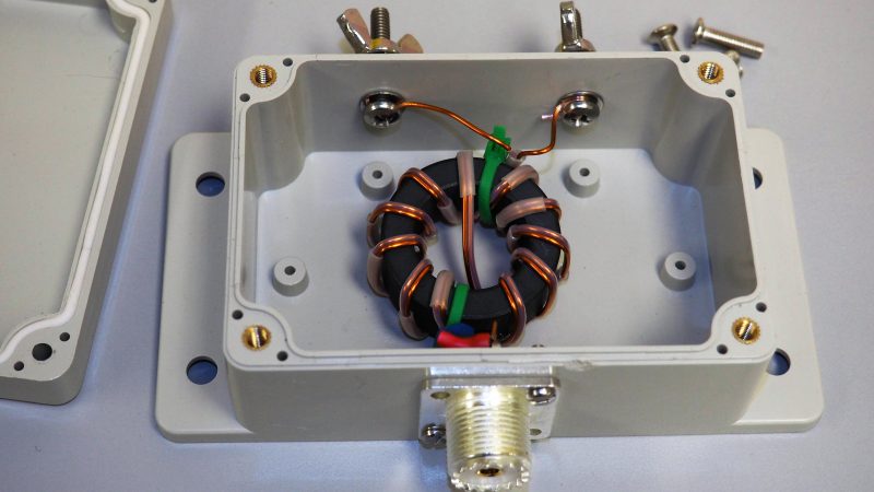
Converting between balanced and unbalanced signals is the job of a balun, and it’s where the device derives its name. For hams, baluns are particularly useful to connect a dipole antenna, which is naturally balanced, to an unbalanced coax feedline. The balun [NV2K] built is a bifilar 1:1 design, with two parallel wires wound onto a ferrite core. To tweak the characteristic impedance to the 75 Ω needed for his antenna and feedline, [NV2K] added short lengths of Teflon insulation to one of the conductors, which is as fussy a bit of work as we’ve seen in a while. We appreciate the careful winding of the choke and the care taken to make this both mechanically and electrically sound, and not letting that RG-11 go to waste is a plus.
With as much effort as hams put into antenna design, there’s a surprising dearth of Hackaday articles on the subject. We’ve talked a bit about the Yagi-Uda antenna, and we’ve showcased a cool magnetic loop antenna, but there’s precious little about the humble dipole.
[via r/amateurradio]


It’s important to note that you should match the 75Ω impedance of the coax with the 50Ω impedance that your radio expects. It’s not mentioned here, but in the Reddit thread says it’s done with an inductor and a capacitor. Since a dipole antenna has a real impedance of about 75Ω, the balun is not doing any real matching here.
Thanks for the precision, I wasn’t understanding how it did impedance matching.
This means the feed lines are “shorted” on both ends? With an LC impedance matching circuit on the 50Ω, I get how it can work, but what about the 75Ω side? same thing?
I don’t get how this matches impedance.
Is one pair of wires on the ferrite is composed both ground and the other one is the line of both sides? If so, how come this is not very inductive?
Or is it the ground of one side with the line of the other with the coupling capacitive with the ferrite here to counteract the capacity?
How high frequency a design such as this one can be expected to work? a few (hundred) MhZ?
http://vk6ysf.com/balun_guanella_current_1-1_image02.gif
I had this argument in HAD once before about twisted wire being used for power and my argument was that the twisted wire electrically evaluates to a bifilar wound transformer (which is what this is) that rejects common mode current while others argued that twisted wire electrically evaluates to two independent inductors.
So to your questions.
1) One side of the wire is signal/ground and the other is balanced signal.
2) It is not very inductive as it’s bilifar wound and the currents are magnetically locked together. One cancels the other so to speak.
3) There is no capacitor at this end – just the transformer.
4) The frequency and bandwidth is dependent on the grade of ferrite in the core. Ferrite cores can be purchased according to grade. In any case this works to very high frequencies. In fact VHF and UHF TV antennas had a 75 to 300 ohm balun. Baluns have very low loss.
5) It’s not obvious but one of the two wingdings is inside a tube which means it’s winding radius is greater than the other. Some clever engineering that I wasn’t familiar with.
More notes: http://vk6ysf.com/balun_guanella_current_1-1.htm
Thanks for the explanation, I think I get it now.
Didn’t he just put some insulation on one wire to keep the characteristic impedance of his line on the ferrite?
I mean, looking at his screw terminals, he does not seems to care this much about wire length… What would that do anyways?
When your wavelengths of interest are tens of meters a few cm of wire means nothing in the grand scheme of things.
Imo it does not change (match) impedance, it is also described a s 1:1 so it does only work a s a balun. It seems to be basically a common mode choke with some capacitive tweaking.
The impedance matching has to be (and is) done at the receiver input.
Baluns like this max out in the 6m band.
These types of balun can also have erratic swr behavior that can damage several types of FET based output amplifiers.
I am sure even the frugal hams attempting skip zone comm can afford the $57 for a decent weather-resistant 50ohm line.
;)
We hams are a very frugal bunch (sometimes far past the point where it makes sense). Depending on the antenna height and distance from the shack, you could be talking about hundreds of dollars worth of coax.
Oy, most of my radios were repaired or old junk, I never had any money so even ladder line was only for making jpoles I tacked down two pieces of scraped telephone conductor wires for feedlines. I had a steel whip antenna I found at an accident site where they had towed off a wrecked 4×4. Always too cheap or poor to afford or even consider a ‘bought’ antenna. ANd yea, it is easy to find junk 75ohm coax so except for mil surplus which I tested we used cable TV stuff for coax and watched the SWR before cranking the power on the amp.
J-Poles are nice… and can perform pretty well if carefully constructed.
=)
This articles mismatched solution is not much better than a simple ladder line option.
a practice abandoned years ago by most sane operators.
Finding heavy carrier-grade exterior coax is not difficult these days due to the LTE roll-out programs.
One can even buy lengths by the pound as scrap for much less if you know when/where to look.
;)
Hams that ever touch a soldering iron != Hams that spend $2000 on fancy digital radio.
Do you know if the 2013 FCC silly narrowbanding rules for ham went into effect or not?
If I recall, most older equipment based on fixed component design would effectively lose 30% coverage, and currently be unable to meet compliance (thus illegal to sell/import/operate many existing repeater/hand-held hardware without an upgrade).
Most will probably have to go digital eventually anyways… just to keep up with the bureaucratic process-driven douche nozzles.
;)
As far as I can tell, the narrowband FCC rules don’t apply to ham radio. There seems to be a lot of debate in the ham community about a voluntary switch to narrow band, with a lot of opinion against.
1) What type of balun are you talking about? A 1:1 toroid? These things are all over both the internet and amateur radio books. If you know something bad about them please… elaborate!
2) $57 could very well be prohibitive. I for one first obtained my license as a college student. I think I spent $40 something for my first radio and had to save up to do that. My first antennas were all either gifts of home-made out of wire.
3) $57? That must be a short cable! Your radio would have to be right next to the window or whatever hole you are using to get through the wall and the antenna right outside that. While such a short length is always a good choice to minimize loss we don’t all have the geography and architecture to allow for such a perfect arrangement. Actually, I suspect that the more sensitive to price one is the less likely they are to have such a location. Or.. maybe you are talking about RG-58. That stuff is reasonable for the short distance within your car but beyond that it’s really just a long resistor. You might as well be suggesting using a dummy load!
4) Ham radio is a hobby with a lot of facets and to each their own… I don’t know what makes it interesting to you. It could be completely different for us yet equally valid. What makes it interesting to me are the possibilities of building things myself and doing things with less. I can buy any sort of internet appliance and use it to chat with people in any part of the world. Ham radio to me is about not just buying it pre-packaged, ready to consume. To just go out and buy everything, already perfectly designed or adapted for ham use… for me that just takes away the majority of what makes ham radio worthwhile. But then… if I had the opportunity to take a ride in one of either the output of some “Junkyard Wars” competition or the latest, most expensive exotic car, fresh off the factory floor… I would chose the former. Not everyone would feel the same and that’s ok.
You cover a lot, so I can only really clarify my own concerns in the time I have:
1. This is not really a Bifilar setup given the winding asymmetry, and understanding mismatched balun S11 parameters is a thick subject already… Kids learning why their power amp keeps blowing $80 FETs would be a poor lesson. It is also highly irresponsible to leave out the custom antenna tuner likely needed to get this badly matched design to even work with any degree of efficiency.
2. Um… Ok…
3. see above for sourcing tips… but it can’t help you if in remote rural areas.
4. part of our club’s hobby is warning students how to avoid breaking expensive stuff, and documenting the best practical solution currently available. I don’t really understand how this article meets either of these criterion..
=)
I’ve thought many times about doing this as I have a lot of good quality 75 ohm cable lying around. I even have a length of 75 ohm hard-line! But.. I’ve noticed that good lengths of used but decent low-loss 50 ohm cable is becoming more affordable at hamfests. I no longer see a need to use 75 ohm.
A few years ago this would have been great to do and write-up. People with established careers probably don’t need that however as prices on components and even whole radios have finally come down younger people could use this knowledge to do things that were previously out of reach. I first obtained my license as a college student and yes, good 50 ohm coax was pretty much out of reach to me then although I could get as much RG-6 as I could carry just by walking past a construction site dumpster!
I do think it would be a lot better to talk about the other end though, how did he match the 75 ohm line to his radio?
Also.. why use a SO-238? If I ever try this I will probably use an F connector. Besides the fact that F should present a better impedance match (probably not important for hf) I think it’s better to keep things that are electrically incompatible with one another physically incompatible. You don’t want to pull this balun out of your junkbox years or decades from now, having forgotten that it was designed for 75 ohms and plug your 50 ohm cable into it! Granted, 75 to 50 ohms is not such a bad match as to be likely to blow a radio but it’s still going to cause inefficiency.
It’s also possible that the radio he’s using is an older tube or tube-hybrid radio. The matching network on those are typically fine with 50-75ohm impedance. For example my radio, an FT-101E has a listed antenna output impedance of 50-75ohm.
Using 75ohm coax is only a 1.5:1 VSWR. SDo only 6% of power is lost due to missmatch.
Some nice low loss 75ohm coax will quickly beat RG58 in even moderate length runs in terms of loss. Many modern rigs also have a built in antenna tuner that will take care of the missmatch anyway.
I have personally used 75ohm coax for various things without problems.
I have even used twisted pair phoneline as transmission line for a 40m dipole.
Back in the days when coax was used for ethernet (10base2, if I remember after all these years), I wired all the computers in my house and workshop with surplus 75 ohm cable. I used 75 ohm terminations (resistors on each end of the coax run) of course. Never a problem. I’d never have done that at work of course. A lot cheaper than buying a bunch of 50 ohm cable.
So if lamp cord can be use for 300 ohm and 75 ohm works for 10b2, I can run it with lamp cord and TV antenna baluns….
Isn’t there something to do with relaxation and excitation or something like that? :-|) Man, what are us boys making our own components going to say to the youth? Kids, they’re not that serious. LOL Don’t hit me in the kidneys, you’re not supposed to hit. Ew Ew ew
10B2 is signal transmission and not power transmission.
I have a bunch of ferrites, but I don’t know their specs (max. frequency, etc). So, how would one make a balun without the ferrite core? Air core would be great.
There are baluns that don’t require a magnetic core, but they have fairly narrow operating bandwidths. You can construct a transmission line balun (such as a bazooka balun or a tapered coax to twin-line transition), or a lumped element balun (e.g. a lattice balun). Unfortunately, both of the options only work over narrow frequency ranges. The lattice balun can also be used to match one impedance to another.
You can wind an air core balun, but they tend to be very inefficient, as the inductance is very low.
Thanks Stephen O. It looks like the TX line balun that you mentioned will work for me, since I need only very narrow bandwidth.
1 ) Google “Ugly Balun”. That’s your air-core version and there are lots of them out there to read about.
2) Try characterizing your ferrites. You could get the Al by wrapping a fixed number of turns of wire around one then measuring the inductance. Don’t have an inductance meter? Maybe you can get ahold of a grid dip meter. Those are nice because they are useful for many things, including but not limited to measuring inductance. I’ve seen some at hamfests for cheap but I don’t know if that is true worldwide. If you can’t get that then maybe just throw a known capacitance across it, then estimate the resonant frequency using a receiver and a noise source. You might even get away with just the receiver and atmospheric noise. Need the maximum frequency? Get it working at a lower frequency then start tuning up and see if it stops working. Just be sure to keep your transmitter on low power and your test transmissions short just in case. Need to know the max power? You might get an idea of that if you know what sort of device they came out of and what part of the circuit they were in. Or.. you could run QRP, then it would be unlikely to matter. Other than that I guess just start low, use short transmissions and work your way up slowly and carefully.
Good luck and have fun!
Thank you for the good pointers. My only factory made signal gen tops out at 5 MHz :) and it is 1970’s vintage. I do have a few that I made myself (in various stages of de-composition :)), so I can use them as signal sources. My scope is modern, up to 100 MHz. For inductance meter I have that small Chinese thingy that also tests capacitors, transistors etc.
For receivers I have RTL-SDR dongle, one modern PLL Chinese radio 0.4-21 MHz, and few shortwave radios I built myself. In few years I will get my ham licence, I hope. Currently I’m into remote telemetry.
I’ve found my Chinese component tester to be a bit flaky on inductors. I wrote an article about this and two other methods of measuring an inductor at:
http://www.buchanan1.net/inductors.html
Interesting, I was wondering the variation in the ferrites also in regards to specification (frequency, impedance and I might not be visualizing in my mind all I need yet to understand) for as “Bill” mentioned in the example of a bunch of ferrites on a coax as a balun. Amazing, the reference to testing each individually and the found quality control batch or within batch variability. I wonder sometimes if the Chinese stuff we get is like “seconds” like the items from the outlet malls. Except… this part of the country or most parts of the country are obsessed with other stuff and activities unfortunately. Then again, I’ve dealt with raw materials QC from China and India… and wow… there are differences in comprehension skills for why the tests need to pass is all I am going to say. :-\
For a 1:1 balun, slip some ferrite cores over the coax. This keeps RF current from flowing on the outside of the shield and acts as a balun without the need to wind a transformer.
https://www.nonstopsystems.com/radio/img-ant/radio-balun1.jpg
I’ve never seen that done before. Are there any specifications for different materials or is your image the spec basically?
You would want to choose ferrite cores that are rated for the frequency range you’re using. I had some left over snap on cores that were rated for something like 100 ohms at HF frequencies, so I used six or so, figuring that the 600 ohms in series with the current trying to flow down the outside of the shield would be good enough. (the photo is something I found on the internet, not my exact balun)
http://www.fair-rite.com sells a wide variety of cores, both solid and snap on. Here’s a direct link to the snap on ones: http://www.fair-rite.com/product-category/suppression-components/round-cable-snap-its/
(Mouser carries them)
(No, I don’t work for them, but I’ve used their cores and EMC labs seem to have a sampling of their products on hand)
https://www.thewireman.com/baluns.html has some beads and balun kits.
Thanks for the references Bill. I was reading about making ferrite and is interesting when looking at other references the “magnetic alignment” kiln processes for when sintering the magnetic ferrite. Some processes the material sinter, grind and re-sinter to magnetically align. Then there is this type which I wonder what the characteristics are:
https://www.instructables.com/id/Make-your-own-Ferrite-to-improve-magnetic-fields/
https://www.youtube.com/watch?v=iXLWu6jSHQU
https://www.youtube.com/watch?v=jAsRp4dvJCU&t=11s
I’m guessing the simplest way to measure the performance of the ferrites made in the above link(s) would be to determine the calculations for the properties to be determined and maybe use some sort of crystal radio like setup and see the effect on the inductor coil. Maybe something like this setup: http://www.crystal-radio.eu/lctest15/enlctest15.htm
Any ideas for a simpler method or more accurate method that is easy?
Well, if you want to use 75 ohm coax with a transceiver, you need a broadband impedance converter at the output of the transmitter. The article is a bit confusing on this point.
This is normally done with a 50:75 ohm transformer. An LC match will work, but only at one frequency.
This 75 ohm balun would go at the other end of the 75 ohm coax, where it connects to the 75 ohm dipole
I once hooked up a CB radio to a dipole made out of two 10′ pieces of metal conduit. I used RG-59 TV coax. The 75 ohm coax and steel dipole presented a really nice 50 ohm match on the CB. I used to talk to my nephew five miles away with a stock 4 watt radio. The antenna worked well. On my nephew’s end, I used a vertical piece of conduit above a metal garage roof as a ground plane, again using 75 ohm coax and matched it to 50 ohms by adjusting the length of the conduit.
Nice box, lousy choice for antenna connector, SO-239? pffft.
He probably chose a SO-239 because it’s easy to buy a PL-259 plug that can fit the thicker RG-59 cable.