It’s been a few years since the introduction of the first Open Source toolchain for FPGAs. You would think a free and Open way to program FPGAs would be a boon for hardware development, but so far we’re really not seeing much in the way of a small, cheap, clever device that brings FPGAs to the masses.
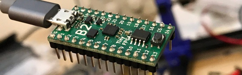
We don’t know if [Luke]’s entry to the Hackaday Prize is the killer project that will do it, but it is very neat. He’s designed a tiny FPGA development board using a Lattice iCE40 FPGA that’s able to program itself over USB. It’s small, it’s cheap, it’s easy to use, and there are working examples of FPGA development using this board.
If you’re thinking this tiny little board looks familiar, you’re right. [Luke] has been working on a similar board, the A-Series, but this latest version has a USB port instead of pins for a JTAG adapter. This USB functionality is pretty clever — instead of using a seperate microcontroller, [Luke] is using the FPGA itself to reprogram the user configuration into a Flash chip. Once that’s up and running, the bootloader is removed and doesn’t consume any FPGA resources.
[Luke] is also working on an amazing hobbyist guide to FPGAs that leans heavily on the Open Source toolchain available for these Lattice FPGAs and his board. That’s a huge benefit to the community, and an excellent entry to the Hackaday Prize.


the hard/sad truth is that the fpga is not for the masses, pyton, arduino is much better suited for them…
FPGAs are a different skillset.
Yes, FPGAs are a different skillset from say Java, Python, C etc.
I think the masses would use FPGAs if they were more common and there were many more user friendly FPGA boards.
Think of the Arduino ecosystem that is based on Atmel chips. Atmel microprocessors existed decades before the Arduino existed and was not common for the masses to use. Debugging assembly programs in AVR studio for Atmel chips can be a challenge. The Arduino project makes it for the masses in through the Arduino SW platform that is basically a modified version of Processing and an easy to use PCB that breaks out I/Os, includes a bootloader, etc.
Also, there is plenty of help online for that platform.
If that type of ecosystem existed for FPGAs, then more people would enjoy the complete joy of multiple lines of code executing in parallel on hardware! Yaay!
Debugging in arduino is still a pain in the rear
and for totally different applications
In many ways FPGAs are more intuitive than Arduino code. When I got my first microcontroller at age 13 I initially struggled with the idea that the processor could do only one task at a time. FPGAs are only unpopular because they’re expensive and programming them is complicated.
Interesting. I would have said that thinking parallel streams of processing is very foreign to most people, but thinking in a straight line to get a task done is pretty easy.
“Parallel streams of logic” might be an accurate way to think about it, but anyone who can understand C can understand simple combinatorial logic and flipflops.
Non-professionals won’t be into designing advanced data-flow pipelines and gnarly carry-lookahead schemes any more than they are currently into writing their own advanced numerical solvers and metaprogramming systems in Python… but it’s reasonable that someone smart enough to do some arduino blinkenlights or if/then logic in a loop should be able to manage a bit of logic.
I suspect that if/when a PLC-style graphical UI for ladder logic becomes available for FPGAs, that that will be the arduino-moment.
The whole “looks like a computer program but it’s actually all happening at once” aspect VHDL (and I presume Verilog) can take a little wrapping your head around if you’re used to the imperitive programming way of thought. When you start trying to do more complicated things and discover you can’t set a signal to 1 in this case and 0 in that case like it’s a variable because you’d be driving it two different directions, that gets maddening.
If you’re not already indoctrinated into linear programming, it’s actually hard to understand why the computer does only one thing at a time.
Because from the beginner’s point of view, they’re looking at the system thinking “I want this to happen AND that to happen, and then while that’s going one this should be happening…” – they’re looking at it from the end result, not the means to get there, because the means to get there is what they’re beginning to learn.
So of course it comes as a surprise that the microcontroller just can’t do some stuff simultaenously, like control ten servos in a synchronous motion. Obviously it’s possible, but one has to carefully interleave the timing with the rest of the program code. An FPGA is not complicated like that.
When I started programming as a kid, I thought you could just tell the computer what you want to happen, so when someone pointed me to BASIC, I just wrote stuff down like “draw a guy”, “move the guy left” and scratched my head over why it threw errors at me. Obviously it should have worked, because I had seen the computer play PacMan, so it must know how to do all that! When I finally managed to program my first game, it turned out the most obvious things like how to draw the guy, or how to track keyboard input, was a complete juggling act of intricate timing and clever tricks to avoid using any conditional statements etc. and the whole thinking process changed.
That’s why I still like analog electronics, because things are happening, and you can just take a piece of wire and stick it somewhere else, and things continue to happen all at once. If you want to add some feedback, you don’t have to start futzing around with maintaining coherent states and time steps and minding your order of execution so the right data gets to the right calculation at the right time – you just take some component Z and place it between the output and the input terminals of your active element, and it feeds back on itself.
Do you think Verilog and VHDL are partly to blame? I’ve been interested in pursuing FPGAs but keep reading that these are most widely used languages and both are archaic and convoluted. SpinalHDL looks promising but not many learning resources available
You might want to have a look at Chisel. It comes with a set of tutorial problems, testbenches and solutions. I recently started playing with it and was able to get everything up and running in an afternoon.
Thanks I’ll take a look at Chisel
Here is an interesting post and comment thread on Chisel:
http://www.jandecaluwe.com/blog/chisel-flawed-approach.html
Be sure to enable scripting in your browser so you can read the dang Disqus comments.
SpinalHDL and chisel are very close related (former one is derived from the latter). So in the end SpinalHDL is better because it addresses a lot of issues chisel have, but chisel is more popular due to it’s academic roots.
Looks like an approach to AI brains!
Actually I’m waiting for the latest *ware to inhabit these FPGAs if they become more common. People do so love hiding things.
Very neat design, although I am a bit confused as to how the actual programing is initiated. I assume some sort of hardware reset cycle would be needed which seems a bit cumbersome, but it could certainly be a handy feature for emergency bitstream updates when in the field to supplement having a traditional jtag programmer in the lab.
Lattice iCE40 FPGAs, like most FPGAs, have configuration logic onboard that allow themselves to ‘reset’ and load a different FPGA configuration file in configuration flash than the original one.
So here the FPGA powers up into a bootloader that can talk over USB and reprogram the SPI flash, and you either tell the bootloader to load the ‘real’ application, or reprogram a part of the SPI flash with your new application.
I assume it’s a two-stage bootloader. I.e. load the USB loader image, then if USB times out load the user image.
Don’t see how you would tell the chip to reset after the bootloader has been flushed out of the FPGA ;-)
In the old days with a rs232 port people would use one of the handshaking lines (DTR usually) to force a reset, but with a native usb port you would always need something listening from the main application for a reset request.
On Xilinx Spartan (and others I’d guess) there’s a mechanism called multiboot that lets the running bitstream force the FPGA to reconfigure itself from a bitstream starting at a different offset into the config flash. I’m guessing that ICE40 has a similar feature.
It also has nice verilog code for USB serial on the ICE40.
I was wondering from the title, how one could program FP gas?
There are two languages that are commonly used – Verilog and VHDL, where HDL stands for Hardware Descriptor Language and V is short for VHSIC, Very High Speed Integrated Circuit. There are Integrated Development Environments (IDEs) for FPGAs that depend on FPGA manufacturer. Intel has their own Quartus IDE, Xilinx has Vivado or ISE and Lattice Semiconductor has the Diamond IDE. The Open Source IDEs are also available for use mostly geared toward Lattice Semiconductor FPGAs.
You don’t need a physical FPGA to start learning the languages. The basic Intel, Xilinx, Lattice Semiconductor and Open Source IDEs are free to download and can simulate the code. Some people start simulating their code in software then invest in development boards to run code on FPGAs that interfaces with other circuits!
Lattice’s Diamond IDE is actually for their “original” FPGAs, the MachXO and ECP family. They also have the iCEcube IDE for the FPGAs they acquired from SiliconBlue (the iCE40 and its siblings).
It’s worth mentioning that so much modern stuff uses Lattice ICE40 chips now because the community reverse engineered the programming method for the the chip. This means it’s possible to make stuff for that one set of chips without installing multiple gigabytes of proprietary IDE to develop for it.
In a similar way to how integer gas is programmed… just with added IEEE-754. ;-)
Now, we need projects using FPGAs to increase demand.
And they shouldn’t be projects that use an FPGA ‘just because’, they should be projects that *need* the gate level speed and/or parallel processing available on FPGAs. Things that really show how FPGAs can solve problems that microprocessors can’t.
That’s a much smaller set.
Radio/Radar is a massive use-case, IMHO. A stable, cheap FPGA target that you can synthesise firmware for from gnuradio will be interesting.
Also: gate-level emulation of ancient chips and microcomputers. There are enough dedicated crazies in that field who want to keep the flame alive that I expect to see all sorts of classic and/or obscure s**t reimplemented in RTL of some form.
If you want hobbyists to launch an avalanche of FPGA projects, they also need to be reasonably easy to assemble.
While there are SOME low pin count devices, most chips have hundreds of pins, and / or close pin spacing.
These lead to PCB designs with multiple layers, and tracks with fine tolerances – all of which drive the price up.
Example: latest Xilinx RF SOC includes ARM cortex-A cores, multiple ADC’s and DAC’s, running at over 2 Gsamples/sec – in a chip with over 1,000 pins. Wonderful chip, massive overkill for hobbyists.
I imagine most future run-ins will be FPGAs being used in existing designs. e.g. computer chip-sets, GPU boards, etc.
There are plenty of breadboard friendly, and thus through hole soldering friendly FPGAs on carrier boards. No soldering these premade carrier boards into a final project for mass production would not be economically feasible, but if you are getting to the point of mass producing something, you are likely going to be having it made at some manufacturer that can use pick and place machines to do all that for you so you could switch to using the bare chip. But for a one off project maybe up to a dozen or two to be made, there would be no problems just permanently soldering something like one of those carrier boards into the rest of your project. bonus it takes care of all the basic support circuitry for you as well.
The pin count on these is never going to go down due to what they are designed to replace, extremely complex logic that it is still not cost feasible to have an ASIC made, or you want to keep it field programmable to future updates. These little low pin count FPGAs really aren’t all that hugely useful. Sure you can do some very simple glue logic on them but you are not going to be doing anything majorly complex on them, they have the capacity to maybe replace a few dozen discrete logic gates. They’re really a hobbyist device to get your feet wet before moving on to the big boy parts. Or maybe useful in prototyping small sections of a design before integrating it into the rest of the design on a big boy FPGA.
Unless space is at an extreme minimum, replacing a dozen discreet logic gates with one of these doesn’t make a lot of sense. You’re probably not really coming out ahead money wise.
I think that, for the lower level designer, 2 ADC’s (instead of 8) would make for a smaller, cheaper device.
Dropping the sample rate from 2Gsps to 480 Msps (chosen for USB 2.0 clock compatibility) would help, too.
Drop the CPU core back to a Cortex-M4 and I wouldn’t be surprised if you could fit the lot into a 256-pin BGA. Which will fit on a 6-layer PCB (4 layers in a pinch).
You’re right – FPGA’s are designed to replace large amounts of complex logic. That’s the problem: sometimes the design you come up with is small, and the only available devices are massive overkill, in terms of features, support requirements, and costs.
For those of you interested in both FPGAs and cryptocurrencies, I would like to point out that Blakecoin is mostly mined on FPGA. Unfortunately its only been ported to a few Spartan-6 based boards, it would be great if someone could port it to more dev boards and different architectures.
the “about blakecoin” lists a couple of minor distinctions with other cryptocurrencies and then … zombie zombie zombie? I don’t understand or is the coin is used to sponsor game development?
The main Blakecoin developer created it to use in a zombie MMO he is creating. However indie game dev takes time and it has not yet been released. I’ll admit Blakecoin is one of the more obscure Cryptos, but it is stable and designed well. For this reason I usually recommend it to people interested in learning about crypto mining and fpga
Would you recommend this type of board to start learning HDL?
Or is a CPLD or SPLD (even if I struggle to find the last one…) better suited? (I know that their architecture is simpler than FPGA)
Or a big fat FPGA is OK, even if I will never use all of his capability or use it in a precise project?
How did you start to learn it?
I also would like to really understand how it works (LUT and so on…) But it’s more a searching and reading thing rather a board selection I guess?
If you want an open toolchain, which I heartily recommend, your choice is down to one chip: the Lattice ICE40 series. $20 gets you a demo kit that plugs into USB. $40 gets you a much more capable chip with a ton more GPIO pins. Either is fine for starters.
We have a tutorial series that’s honestly a bit advanced if you’re just starting. This tutorial is looking really great for the total beginner, but it’s not finished yet.
If you want to get really deep into FPGAs, we’ve got a post coming up tonight with a video that you should really watch. It’s an hour long, but it’s the best top-to-bottom overview of (the Lattice) FPGAs that I’ve seen.
Awesome! Thank you for the infos!
Here is another tutorial:
http://www.fpga4fun.com/
Cheers!
“Open Source toolchain for FPGAs”… I guess a better wording would be “Open Source toolchain for one specific FPGA”. The unfortunate truth is that currently there are no existing open source toolchains for FPGAs in general. Having reverse-engineered the bitstream for one specific FPGA is impressive in itself, but not really something we can count on in the long term.
It’s not that specific. Yosys and arachne-pnr are not tied to ICE40 peculiarities. You can port them to other FGPA if you know the fabric specs and reverse engineered the bitstream.
And even with that you still have a toolchain that is not endorsed by manufacturer on some specific topic like timing closure and power analysis (the timing closure is itself a showstopper for any serious work).
I spotted coolrunner 2 boards for XBOX modding at £4 on ebay (cheaper alternative if you have a programmer)
Hey, I saw those too. I found two issues looking at these Xbox boards: 1) could not find a schematic or other documentation, and 2) too few pins broken out to be really useful.
In the end I ordered some $15 dollar CPLD boards from seeed. The problem with those? There’s no onboard clock, only a padout for an oscillator. The TinyFPGA A-series probably would have been a better choice, since the lattice XO2s have on-chip oscillators. In either case you still need an external JTAG programmer in a compatible flavor.
If someone really wants to learn FPGAs, I recommend one of the dev boards from the big vendors. There are many tutorials and examples available for these boards. The tools are high-quality and free (to a point), and supported by discussion boards. The Arty is great for Xilinx, and the DE10-Lite is great for Altera.