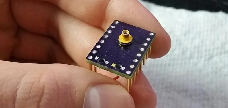
At first glance, [Dean Gouramanis]’s stepper driver module for 3D printers looks like just another RAMPS-compatible stepper board. Except, what could that gold-plated copper peg sticking out of the PCB possibly be? That would be [Dean]’s PowerPeg Thermal Management System that he built and entered in the Hackaday Prize competition for 2015, where it rocked its way into the Finals. It’s a thermal connector peg that attaches to a variety of heatsinks so you can swap in whatever sink fits the bill.
In the case of this project, [Dean] created a custom PCB that accommodates the PowerPeg connector, onto which the heat sink screws. Needless to say, he machined his own heatsinks to go with the pegs, though it looks like you could use any sink with enough surface contact that can be secured by the same #0-80 screw.
You shouldn’t be surprised that hackers obsess over heatsinks. This heatsink tester project we published helps determine which sink to use. Another post gives all the ins and outs of ordering a custom heatsink.


I want to see someone test various extruded aluminum heat sinks as they are stock. Then glass bead blast them everywhere except on the thermal contact surface and test again to see if the bead blasting make any change, good or bad.
My theory is that the roughening increases the surface area, thus improving the ability to both radiate and conduct heat to air flowing past. Of course the surface will rapidly develop a thin oxide film, but that should be thinner and perhaps less insulating than the film produced during hot extrusion and the anodizing process on anodized heatsinks.
Another test to do would be removing the anodizing on the contact face of anodized heat sinks to assess whether or not that is a detriment to performance.
would be good to know – because a smooth surface aids the laminar flow of air past the surface – if not forced with a fan. So how this would compete with the increased surface area for sinks with and without fans would be good to know…
Googling reveals many disussions on shiny vs smooth for the matng surface (grease fills the tiny gaps) but not for basic heat transfer to the surrounding air.
as usual – all been done before…
– https://en.wikipedia.org/wiki/Heat_sink
– http://www.mtarr.co.uk/courses/ami4817_dti/restricted/u14/index.asp
– https://www.slideshare.net/shafie_sofian/transfer-of-thermal-energy
rough, black, better
It doesn’t matter for natural convection. The boundary layer is too large and insulative for any changes in surface texture to matter.
I tested an anodized heatsink and an anodized and then powder coated heatsink side by side and got no noticeable variation between the two, even though the powder has a rather low thermal conductivity.
I then cut out half of the fins on one heatsink, and did another comparison. I got a ~20% decrease in temperature. This seems counterintuitive, but the boundary layer is what defines how efficiently surface area is used, and if your fins are too close together it chokes off any airflow. Getting the proper fin spacing matters far more than surface conditions ever will.*
In this particular case the fins were pointing straight up with the base horizontal, which is the worst orientation for convection. Cutting away strips of the base such that 50% of each fin overhung the base I was able to reduce the temperature by another ~20%.
There is a lot to selecting a proper heatsink and I may try and write a hackaday post on how to select the proper heatsink, get the most out of your heatsink, etc if there is interest. Basically I would like to come up with a little project, maybe a dummy load, and walk through from part selection all of the (simple) math involved to determining what size heatsink you need, how to get the most out of it (orientation, ventilating enclosures, fans, etc.) and other general considerations.
I’m kind of short on time right now so I just spewed words into the comment box and didn’t proofread anything, so hopefully this doesn’t suck.
*If you’re heatsink is physically large, a surface coating such as anodization, which has a very high coefficient of thermal emissivity, will allow you to radiate heat through black body radiation. The math for this is pretty simple, but you have to know that the vast majority of the surface area of your heatsink doesn’t work for this, because it just radiates to another part of the heatsink and merely evens out the temperature, with no cooling effect
+1, yes please Murdock. There’s an awesome free textbook, appropriately named A Heat Transfer Textbook. I relied heavily on it during my degree. I think people with a predominantly electronics background would gain a lot from the kind of article you’re thinking of doing.
Two words. Boundary layer. There’s no magic that hasn’t been used already.
You can optimize your design for natural convection though and get something like 40% more heat dissipation, fairly easily.
I’d question the thermal conductivity of this design.
Tom,
Tom, there were several application tests documented on hackadayio. The Peg may look brass, but it is solid copper with gold plating. Here is a link:
https://hackaday.io/project/6874/log/21457-measuring-absolute-thermal-resistance
Why?
I agree with Murdock and dcfusor2015. Heat transfer into air creates a layer of kinetic air around the heatsink. Your total ‘watts out’ (performace) relies on that air flowing away from the heatsink. The rough surface from glass bead is much thinner than the boundary layer.