When building a radio transmitter, unless it’s a very small one indeed, there’s a need for an amplifier before the antenna. This is usually referred to as the power amplifier, or PA. How big your PA is depends on your idea of power, but at the lower end of the power scale a PA can be quite modest. QRP, as lowe power radio is referred to, has a transmit power in the miliwatts or single figure watts. [Guido] is here with a QRP PA that delivers about a watt from 1 to 30 MHz, is made from readily available parts, and costs very little.
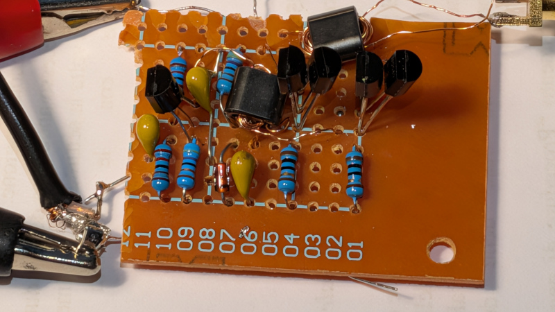
Inspired by a circuit from [Harry Lythall], the prototype is built on a piece of stripboard. It’s getting away with using those cheap transistors without heatsinking because it’s a class C design. In other words, it’s in no way linear; instead it’s efficient, but creates harmonics and can’t be used for all modes of transmission. This PA will need a low-pass filter to avoid spraying the airwaves with spurious emissions, and on the bands it’s designed for, is for CW, or Morse, only.
We like it though, as it’s proof that building radios can still be done without a large bank balance. Meanwhile if the world of QRP interests you, it’s something we have explored in the past.


I enjoyed this article. Nice little project.
On the topic of simple radio circuits, this nonselective AM shortwave radio reciever circuit is easy to make and some fun to play around with (Site is in German): https://www.b-kainka.de/bastel14.htm
Interestingly it seems to exploit the miller effect capacitance of the bipolar transistor as part of the oscillator.
I think that’s brilliant you found a niche in life u make me proud….blindy
Class C is good for more than just CW. [Guido] himself says he’s using it for FT8. Class C is good and standard for FM transmitters too, though you’re not likely to be (legally) transmitting any FM in the bands this can operate in.
FT8 is constant amplitude frequency shift keying, in other words, FM. Even if you transmit it by letting WSJT-X generate beeps and boops fed into a transceiver in USB mode. So yes, even a Class-C biased amp can make a perfectly clean signal on FT8 – if you clean up the harmonics with an output filter, wherein, of course, lies the rub.
Kinda-sorta. FSK is distinct from FM, generally considered for continuous-spectra content. FT8 is very much discrete frequency tones. The FSK spectrum looks nothing like a FM spectrum.
Technically FT8 is ITU designation 2K50J2B (2.5 kHz, single sideband-no subcarrier, digital, machine data), even though it occupies a tiny fraction of that 2.5 kHz channel.
Audio-grade FM occupies a much wider bandwidth. Amateur radio channels (in Region 2 anyway) are 20K0F3E (20 kHz, FM, analog, voice). Narrower channels can exist, but not narrow enough to justify allocating chunks of HF spectrum for it.
“QRP” with an amplifier. Depends on the gain, I suppose.
Depends on the power output, not the gain. I have a 70 dB gain amp that puts out less than a watt. I also have a 20 dB gain amp that puts out 1.5 kilowatts. Which one is QRP?
Less than 5-10W (37-40 dBm) is generally considered QRP.
1.5 kilowatts is a driver.
I say that as someone whose built an amplifier that has 20 dB of gain and takes 225 watts pep of drive for full Pout :)
WP2ASS / ex KD6VXI
Funny you should say that, because that’s where this amp came from: It was part of an amp with a 20 kW final, but I don’t have a way to power that, so I separated them. 1.5 kW is my legal maximum anyway.
The circuit this design is based on, is apparently a linear amplifier according to the original creator Harry Lythall.
The output of Guido’s amplifier has a lot of harmonics. That’s to be expected if the input is connected to a source which has a lot of harmonics, such as the output of an SI5153.
I’m no expert in power amplifiers, but that schematic doesn’t look like a class C amplifier to me.
Personal taste: the signal ground should be along the bottom edge of the schematic, not halfway around the schematic.
It’s not Class C it’s linear. Look at the centre tap to transformer for biasing.
1980’s vibes.
Instead of using a strip board it may be better to use a RF box with air-wiring or Manhattan style so components are spaced out in 3D. This reduces stray capacitance between traces that you’d normally get on a PCB. At high frequencies, a PCB trace can accidentally act like a capacitor or an antenna, “leaking” the signal where it shouldn’t go
There’s a similar low cost QRP amplifier here but it uses a different topology
https://siliconjunction.top/2025/12/31/sot-223-hf-lba-an-open-source-high-frequency-linear-buffer-amplifier/