It is over a decade since the RepRap project was begun, originally to deliver 3D printers that could replicate themselves, in other words ones that could print the parts required to make a new printer identical to themselves. And we’re used to seeing printers of multiple different designs still constructed to some extent on this principle.
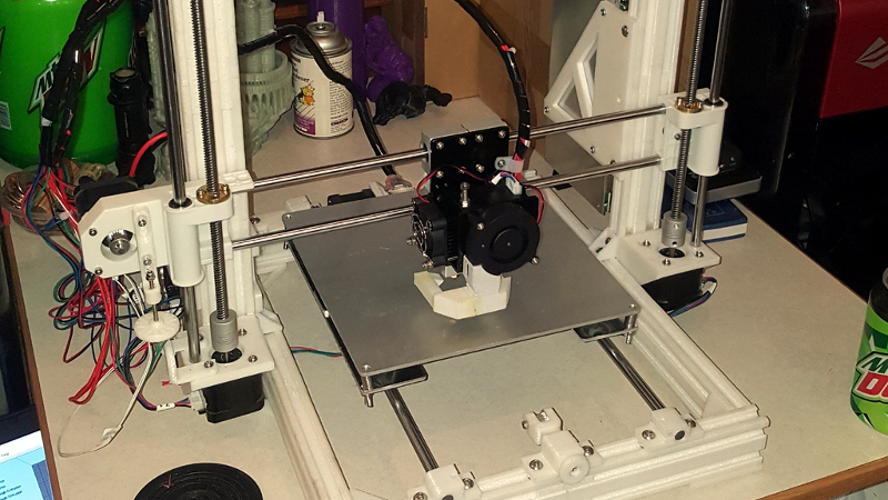
The problem with these printers from a purist replicating perspective though is that there are always frame parts that must be made using other materials rather than through the 3D printer. Their frames have been variously threaded rod, lasercut sheet, or aluminium extrusion, leaving only the fittings to be printed. Thus [Chip Jones]’ Thingiverse post of an entirely 3D printed printer frame using a 3D printed copy of aluminium extrusion raises the interesting prospect of a printer with a much greater self-replicating capability. It uses the parts from an Anet A8 clone of a Prusa i3, upon which it will be interesting to see whether the 3D printed frame lends the required rigidity.
There is a question as to whether an inexpensive clone printer makes for the most promising collection of mechanical parts upon which to start, but we look forward to seeing this frame and its further derivatives in the wild. Meanwhile this is not the most self-replicating printer we’ve featured, that one we covered in 2015.
Thanks [MarkF] for the tip.


There have been many printers with printed frames in the past, so nothing new in that respect. Though an interesting angle the creator has taken here to essentially swap real aluminum extrusion for printed.
Been thinking of using/making similar 3d printed ‘extrusions’ (<–funny when you think about it) to extend the aluminum extrusions on my 3d printed, and increase its print volume.
Like turtles, it’s 3D prints all the way down.
Except it’s like photocopying something over and over or saving using the jpeg file format.
https://cloudinary.com/blog/why_jpeg_is_like_a_photocopier
Indeed.
The tolerance ‘errors’ (drift) would be cumulative, and usually in the same direction, so by the fourth or fifth generation there would be a significant difference. How big a difference would depend on the original tolerances.
Would they, though? As long as the distance per step of the print head remains the same, it should be fine. Even if, say, the X-axis pieces kept getting longer, that doesn’t mean the next generation would scale up its prints in the x-axis. It would simply have extra room on the x-axis. The print head would still be moving 1:1. The motors and belts aren’t printed.
Especially built this way using sliding connectors on “extruded” rails; it would be up to the assembler to keep the dimensions the same and compensate for any distortion. Just keep it square and compare measurements to the original. Now if it was printing in one piece or self-assembling, then there would be a problem with drift.
If that is the case, how did we manage to go from clubs and stones to high precision CNC? Clearly it is possible to construct machines of increasing precision.
hmm…
The old ‘building the tools to build the tools’ chestnut the fanboys like to trot out whenever someone dares to suggest that it’s possible that 3D printers may not be the best thing since sliced bread.
This is not manufacturing high precision tools to within a specified tolerance, which will in turn be used to manufacture other high precision tools to within a specified tolerance.
This is a very specific case of using a machine to copy itself.
Because measuring and feedback can allow us to do so. But if the printer axis is printed skew, there’s no way for the printer to measure this and correct. Of course, you could measure manually and code some correction into the system.
“Clearly it is possible to construct machines of increasing precision.”
Of course it is. You have to use the right tools and techniques though.
I fail to see how this is relevant. You are not copying a copy then coping from that copy or copying the original in a compressed format (JPEG). Even if what you are suggesting did translate to 3d printing, you are printing from an original design or more precisely an exact copy of the those files and then creating a gcode file to use in your printer. What you guys are suggesting is ludicrous.
Not me, and two years ago, but I think this comment sums my feelings up well.
“Every printer is (or should be) calibrated before printing usable parts. If you 1st generation printer has been tuned so that a 20mm cube is really 20mm on all sides, the extrusion volume calibrated properly, and the usual quality gremlins worked out, then the 2nd generation should have an equal chance of being calibrated to the same quality standards.
The photocopying a photocopy generational degradation analogy doesn’t work here.”
https://hackaday.com/2015/09/12/the-most-self-replicating-reprap-yet/#comment-2712235
i’m not trying to be critical- you’ve done a lot of good work…. but
When you can print any shape you want, does it really make the most sense to print a t-slot configuration? Aluminum t-slot is great because you can connect stuff anywhere along its length with t-nuts, but with this printer design you already know where everything is going to bolt to the frame, so all those slots add up to a lot of extra print time and plastic, and probably reduced rigidity. I suspect that circular tubes with low infill % would be more rigid, print faster, and use much less plastic. You could always print holes every 20 mm or so to easily attach things to it.
Corner braces are needed in many t-slot frames because the designs use too small t-slot which is not sufficiently rigid without the bracing, and because it’s difficult to cut it squarely. You don’t have those problems- you can design and print parts that are rigid enough without corner braces. Why not just print a more rigid frame and skip the plates and hardware? Motor and guide rail mounts can be integrated right into the frame pieces.
T-slots are economical due to extrusion as a manufacturing method. Recreating it with 3D printing is limiting yourself to inexpensive geometry when 3D printing does not have that limitation. Also extruded aluminum metal is stronger, more dimensionally accurate, as well as faster and cheaper to produce. Interesting experiment though.
I’ve followed some of Chips work for awhile, While its true that these are just copies of existing designs its the fact that he went ahead and did it despite everyone telling him it wouldn’t work. He went through several versions till he got details like the butt connectors for the extrusion to work so you can print longer pieces in short sections and they will align and have some added strength, the center area of the extrusion has a 8mm hole running its length so a plain metal rod can be added to give it more rigidity, although in his build he only used rod in the Z sections. I think he did very good work on this and cant wait to see what he tries next.
This is a great idea, but the execution could have been better. 3D printing offers the ability to create shapes that cannot be created with traditional manufacturing processes. The frame shape could have been much more organic in other words.
I don’t get the point here. 20×20 alu extrusions are available for less than 5€/m. And much stronger than anything printed.
I believe that the cost is about 1/3 that of aluminum, add in that setting up an account with Misumi for home delivery can be a major hassle and this is a good way to test the design and see if you like it.
Why Misumi if it’s a major hassle?
I usally buy them at motedis.de – but there are at least 5 other European shops with good prices. Don’t think that it’s completely diffrent in other parts of the world.
1/3 cost for the printed part – well, maybe if you count the filament only and no print fails…
It’s like printing screws. Of course I could, but not really useful.
Not to be critical, but, how’s that Y-axis moving? Did they perfect transparent belt technology?
“Self replicating” is a philosophy.
At some point most of us got off that philosophical train and decided we just wanted to print stuff.
The Dollo 3D printer has a 3D printed frame and uses 3D printed herringbone racks and pinions..
I had a 3D printer with a 3D printed hot-end.
Not saying it worked very well, or anything…
Great place for one of those tilted bed, infinite build volume jobs. Butt splices are pretty lousy at best. Or friction weld them.
Better than acrylic, that’s for sure. Can’t argue with that. A8’s are definitely better off.
It’s great these beams can be reused to build something different later on. It’s also easy to change or upgrade parts.