The Casio SK-1 keyboard is fairly well-known in the “circuit bending” scene, where its simple internals lend themselves to modifications and tweaks to adjust the device’s output in all sorts of interesting ways. But creating music via circuit bending the SK-1 can be tedious, as it boils down to fiddling with the internals blindly until it sounds cool. [Nick Price] wanted to do something a bit more scientific, and decided to try replacing his SK-1’s ROM with an Arduino so he could take complete control it.
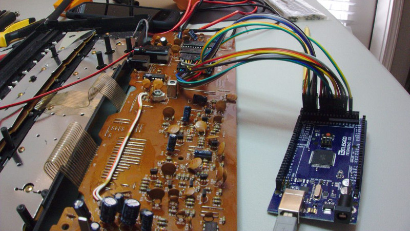
That’s the idea, anyway. Right now he’s gotten as far as dumping the ROM and getting the Arduino hooked up in place of it. Unfortunately the resulting sound conjures up mental images of a 56K modem being cooked in a microwave. Clearly [Nick] still has some work ahead of him.
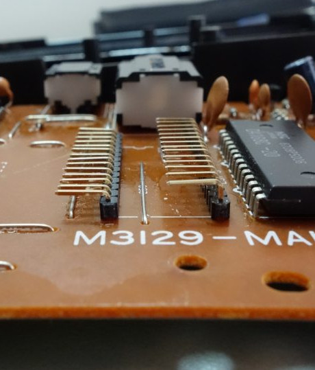
For now though, the progress is fascinating enough. He was able to pull the original NEC 23C256 chip out of the keyboard and read its contents using an Arduino and some code he cooked up, and he’s even put the dump online for any other SK-1 hackers out there. He then wrote some new code for the Arduino to spit data from the ROM dump back to the keyboard when requested. In theory, it should sound the same as before, but with the added ability to “forge” the data going back to the keyboard to make new sounds.
The result is what you hear in the video linked after the break. Not exactly what [Nick] had in mind. After some snooping with the logic analyzer, he believes the issue is that the Arduino can’t respond as fast as the original NEC chip did. He’s now got an NVRAM chip on order to replace the original NEC chip; the idea is that he can still use the Arduino to reprogram the NVRAM chip when he wants to play around with the sound.
We’ve covered some pretty fancy circuit bent instruments here in the past, but if you’re looking for something a bit easier to get your feet wet we ran a start-to-finish guide back in the Ye Olden Days of 2011 which should be helpful.


The arduino could easily replace the rom chip. You just have to program it properly instead of using that digitalWrite crap.
Eh, emulating a ROM is not really within 8-bit microcontroller capability.
The Atari 2600’s Harmony cart emulates a 8 bit ROM at 1.2MHz using a 70MHz ARM.
This is on the cusp. The ROM is 200ns access time and the Arduino has a 62.5ns clock cycle so it’s doable with tight code and interrupts. Assuming the Arduino is one instruction per clock and not 4.
Nah, definitely not. Atmega interrupt latency, plus the time to copy the value from the pins to a table and do the lookup and relay the value back out? Much too slow.
Keep in mind that the access time of the 2600 is a glacial 420ns.
If it’s doable then without interrupts in a very tight polling loop. Interruots to be used for the external interface, if you want to reprogram it. But an “EPROM emulator” concept with an NV RAM is much better.
Is replacing the ROM of an electric synth with what amounts to an emulator actually circuit bending? Not that it isn’t interesting… of course the device already is a music instrument, and the other link is a modification of a music instrument also. Seem more like electronic music instrument hacks rather than circuit bending, in my opinion. I was under the impression that the cool/clever aspect of circuit bending was to modify circuits that aren’t already designed to be synthesizers. Not a huge issue, and cool hack in any case!
I can remember modifications for very Casio “noise makers” like the VL-Tone. I can almost picture some saying “well I guessed at this and fiddled at that”, in part because information was scarce (about the ICs, about the equipment) so “fiddling” was the way to go.
That seems to fit the notion of “bending ” as it came to be used. Changing something, often by trying, to get some other feature. I’m not sure it really is about “making a synthesizer out of something else”
Michael
Resistors. Diodes. Capacitors. Inductors. Long ago, the four passive components lived together in harmony. Then, everything changed when the Diodes attacked. Only Ghazala, master of all four passive components, could stop them…
this looks promising! will love to follow along with the progress on this (i think i have 8 or 9 sk1 keyboards to play with). i would also love to see soneone hack the cartridge slot like you find in the pt82 (and others)…
He’s on the right track but that CPU seems to be from the 1980’s (from memory).
I seem to remember it being used in dot matrix printers of that era and if memory serves me correctly it was most often a Quad Inline Pins package.
The next step is to write some code to separate the data ares from the instruction areas.
create a byte array the size of the ROM (or an eighth of the size as a but array) to store binary values that act as a flag for either code or data.
create a variable length double byte array as a code thread stack to store ROM addresses
Find all the binary values for branch instructions.
Start reading the ROM from &h0000 and mark each address as code in the code flag array.
When you reach a branch address then push that address into the stack array.
When you read an address that has already been read then drop that thread, pop an address from the stack array and start from that address, When there are no more addresses in the stack array your done and the flag array will tell you which addresses are code. The code can be disassembled and then you can start looking at the data.
Now write another program to highlight any read instruction that read from areas that are not flagged as code and you will get an idea of how the data is interpreted.
FWIW, The ROM sample data begins at byte offset 2816 in the bin file. Just load-up the bin file in an audio editor of your choice as unsigned 8-bit audio. Sweet 1980’s samples.
Oh, and mono…clearly mono.
hmm, seems allot of samples are missing from this? or maybe its remodulating other ones.
Possibly, you’ll notice there are some fundamental tones in there, like sine, organ, horn. I’ve never played with an SK-1, so I don’t know what sounds it makes from the factory…always did want one as a kid, though. But once I discovered MOD music, it was moot.
Wow, you know this unit well. I couldn’t even find asm info for the CPU. It seems to be a custom CPU made by Casio and they didn’t release a data sheet for it.
Where did you get your info?
I took a quick look in a hex editor, and noticed the familiar signatures of unsigned 8 bit mono samples…loaded it into an audio editor and there they were :)
Final list of sample offsets / lengths from that bin:
Offset Len
0x0B00 256
0x0C00 128
0x0C80 128
0x0D00 128
0x0D80 128
0x0E00 256
0x0F00 128
0x0F80 128
0x1000 4096
0x2000 8192
0x4000 4096
0x5000 4096
0x6000 8192
Architecture appears to be little endian. An index of samples appears at 0x85C:
00 20 – sample 10
00 60 – sample 13
00 10 – sample 9
00 40 – sample 11
00 50 – sample 12
80 0f – sample 8
00 0b – sample 1
00 0e – sample 6
I love the SK-1 and keep thinking someone could make headway with a “modern” revision.
they have, its called an op-1.
Just a general ‘bending question here; Can a shift register with a pot hooked up to the clock reading a piano matrix be used as an arpeggio generator?
My two cents worth – If the goal is to build a ROM emulator (RAM???), then this is an interesting but round-about way of doing it. If the goal is to bend sound, why not emulate the ROM in a much simpler way (static RAM shared by the Arduino, or similar), so the real task of bending sound can be tackled. Just saying…
If it’s fast enough, you could even modify it in the background. Similar to the combined access of CPU and VIC 2 in the C64.
He could use a “dual ported SRAM” like this: https://www.idt.com/document/dst/7007-data-sheet
The Arduino can take all the time he wants to write content and the keyboard can read as fast as it can…
It’s most likely that the Oki SoC used in the SK-1 has on-board ROM. The external ROM looks more like it just contains an interpreted bytecode, plus samples.
After looking at the ROM dump, it looks a lot like the the external ROM only contains samples and interpreted bytecode. The MSM6283-01GS likely has an internal program ROM. Other Casio keyboards use other variants with different suffixes, like the MSM6283-05GS in the DM-100 dual-manual keyboard. It’s likely that the different suffixes are the same SoC with different internal programs. It would be good at some point to collect all the different versions of the MSM6283 SoC and decap them to identify the CPU core and extract any internal ROM data.
I looked around hoping to find info on this CPU.
I did find info on other chips in the MSM series that had internal ROM but they were mostly speech synths chips.
So I ask why you say that this perticular chip has internal ROM and that the external ROM has interpreted bytecode?
The manual says –
“The capacity of ROM is 256Kbit and contains the program for system execution”
256kbit (or 32kByte) is a lot for interpreted code.
Does this ROM dump contain any info about start and end loop points for the samples? I’ve actually extracted the thirteen individual samples into separate files just for the fun of it.