Perhaps the most important consideration to make when designing a battery-operated device of any kind is the power consumption. Keeping it running for longer between battery changes is often a key design point. To that end, if you need to know how small programming changes will impact the power consumption of your device then [Daniel] has a great tool that you might find helpful: an ESP8266-based live power meter.
The power meter itself is battery-powered via a 600 mAh battery and monitors an e-paper module, which also displays information about power consumption. It runs using a NodeMCU and measures voltage and current across a 100-ohm resistor to calculate the power use, although the resolution does start to get noisy when the device is in standby/sleep mode. One presumes this could be solved by changing the value of the resistor in order to get more accurate measurements at the expense of losing accuracy during moments of high power consumption.
While this power monitor was built specifically to monitor power consumption on this particular e-paper display project, it should be easily portable into other battery-based systems that need fine tuning in order to maximize battery life. As a bonus, the display is already included in the project. There are ways of getting even more information about your battery usage, although if power consumption is important than you may want to stick with a more straightforward tool like this one.


Couple of things to think about when measuring current consumption of very low power devices: Bandwidth of the current sensor and sample rate. Often very low power devices have widely varying [relative] current consumption over short intervals and it’s possible to for the measuring gear to completely misread the device’s true power draw. Higher sampling rates and/or hardware or software filtering may be required. In addition, if the device has varying current consumption that spans a decade or more (for example uA sleep to mA operating), the measuring device may run into trouble at either the low or high end of its capability. Some measurement systems have multiple channels to optimize sensor gain vs current.
Wise words. In today’s switching power supplies and wide current dynamic ranges, integrating a RMS value is a pain.
Initially I was afraid they just use the ADC on the ESP chip.
But it uses an INA219 module that can do about 11904 samples/second in 9bit mode, but also has averaging modes for higher 12bit resolution.
That would be good enough for general power monitoring of DIY projects.
It doesn’t claim to be a lab-grade tool.
Something I have done in the past is to put a low pass RC network parallel to the series resistor, and then measure the voltage across the capacitor. For instance, put a 10K resistor and 10uF capacitor in series, and then put that circuit in parallel with the current sensing resistor.
What this circuit will do is introduce an averaging time of 0.1 seconds. In other words, it will smooth any peak faster than that into an average voltage so that your sampling rate can be lower.
The voltage over the capacitor will be very similar to the voltage over the shunt resistor, except for a tiny bit of voltage drop between the 10K resistor and the internal resistance of your network (and capacitor). If that bothers you, you could feed the capacitor value into a suitable opamp with a very high input impedance, and configured as a voltage buffer. Of course you need to then battery power the opamp.
For the best results you should use a capacitor with a low leakage current such as polypropylene, and of course use a measurement instrument with a high input resistance and floating or differential inputs.
This! The influence of small programming changes can be simulated for microcontrollers when battery budgeting software is available (see for example http://www.microchip.com/SWLibraryWeb/product.aspx?product=nanoWatt%20XLP%20Battery%20Life). However if the programming has been performed somewhat sensibly, the effect of programming optimization will in my experience be secondary to that of hardware optimization (low quiescent current voltage regulator, etc)
TI builds an interesting solution to this into some of their Launchpad boards. Rather than measuring current through a shunt resistor and integrating it, they run the target from an instrumented buck converter.
The buck converter is an MSP430 (of course) with a little power MOSFET and some passives, and I think it uses a fixed pulse width, varying the pulse frequency to regulate output voltage. Since the energy delivered by each pulse is more or less constant (assuming the voltage stays in regulation), counting the pulses gives you a measurement of energy consumed. Filtering short load bursts is naturally handled by the output capacitor.
I haven’t cared enough to try yet, but this seems like something that shouldn’t be too hard to implement.
Very clever. Or do it with a switched capacitor for basically the same effect, just different parts.
Shouldn’t the Shannon Nyquist theorem still apply? In that case you need sampling double the rate of your fastest transition frequency (primary tone)? Alternatively maybe you could use an analog integrator?
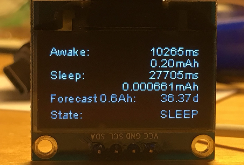
I would not trust this device. It shows “0.000661mAh” and “forecast 0.6Ah”
It shows a forecast in days for 0.6Ah battery.
battery of device being tested is (0.6Ah) and maybe that shouldn’t be on the screen? or ‘mA’ instead of ‘mAh’ for the current draw/usage? i don’t know and can’t care about the mistrust, but i do wonder what was meant.
That is not an e-Paper display. That’s on OLED.
It’s for MONITORING an e-paper module’s power consumption. The display pictured here is not the one being tested.
The original blog post has been edited. The current shunt resistor was .1 Ohm, not 100 Ohm, which seems a little more reasonable.