Modifying the Amiga 500 to speed up access to RAM in a memory expansion pack is a well documented procedure, with guides on the process written in the early 1990’s when the hardware was only a few years old. But as they were written for contemporary hardware, they make no concessions for how one should be treating a vintage computer that’s now over 30 years old. In 1993, cutting traces on the Amiga 500 motherboard was just a last ditch effort to eek a few more months of service life out of an outdated desktop computer. But in 2018, it’s kind of like when that old lady tried to “restore” a fresco of Jesus in Spain; it might be done with the best of intentions, but you still screwed the thing up good and proper.
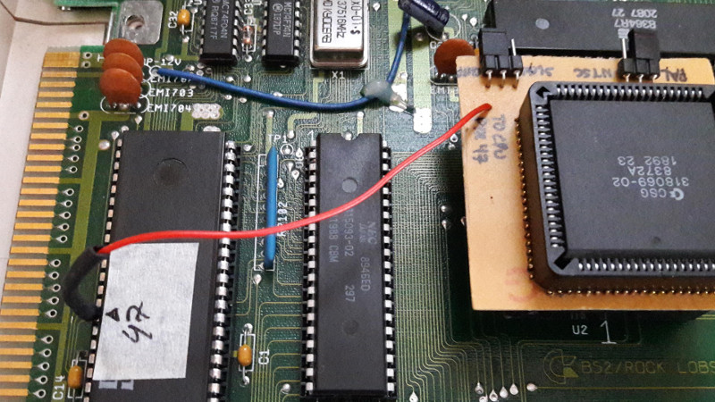
 Such things don’t fly over at [Inkoo Vintage Computing]. There you can find a guide that details the impressive lengths one can go to if they want to perform the classic modification without any irreversible changes to the motherboard. To avoid the cut traces and soldered bodge wires, this version of the modification makes use of a novel adapter that breaks out the necessary connections on the 8372A chip.
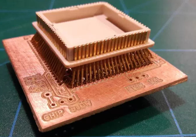
The adapter is simply a homemade PCB with both male and female plastic leaded chip carrier (PLCC) connectors. The few pins on the chip that needed rerouting are exposed as solder pads on the adapter for easy wiring. There are even a couple jumpers on the adapter to turn the modifications on and off.
Not surprisingly, the trickiest part of building this adapter was sourcing the antiquated PLCC connectors. Assuming you can even find them, you are then left with the challenging task of soldering them together. Judging by the pictures on the [Inkoo Vintage Computing] page, it’s no walk in the park.
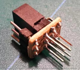 Another similar arrangement is used in the expansion bay of the Amiga, where a pin is virtually “cut” in the connector. A tiny PCB is soldered to a 3×2 header to reroute the signals, and another jumper is used to enable and disable the pin. Luckily, the long pins on the Amiga memory expansion are forgiving enough that the little board can fit in between them without breaking electrical contact.
We’re no stranger to the Amiga 500 around these parts. We’ve covered how to get the 1987-vintage machine online in the 21st century, as well as employing a Raspberry Pi to emulate the original floppy drive. You can even make your own faux-Amiga with a 3D printed case, if you suffer from a sort of existential dread when working on a computer that’s older than you are.


That’s a nifty design for the Agnus adapter and the modification in general. Well done.
With regards to the article above, I believe the modification isn’t to speed up the internal RAM expansion speed but to use the RAM expansion as additional chip memory. The RAM expansion is already sitting on the chip memory bus but can’t be addressed by the on-board coprocessors on his rev 3 motherboard.
Also, the space for the pin 32 interceptor board isn’t because the RAM expansion board has extra long pins–it’s the additional 12×2 and 13×2 connectors that were added on either side.
Thanks!
You are correct about both points.
The issue is that normal Amiga 500 trapdoor RAM expansion can’t operate as “chip RAM”, i.e. be accessible by Amiga’s special purpose chips (graphics, audio etc.), but the motherboard needs to be modified for this. The modification part applies also to rev 6 and rev 5 motherboards, but it’s slightly less destructive on those motherboard revisions as there are ready-made solder pads.
Also the extra space to fit the PCB in the connector is because the connectors I used have extra long pins.
So making the expansion into “chip” RAM doesn’t speed it up? I would think it would be the fastest since it has direct access to the CPU.
Unless I’m not understanding the differences.
Chip RAM – RAM that the chipset can access, CPU is usually less prioritized than chipset.
Slow RAM – RAM that only the CPU can access but sharing the chipset bus making it as slow as chip RAM.
Fast RAM – RAM that only the CPU can access with no access penalties.
The mod is just allowing some additional address pins on newer releases of the Agnus chip to be used changing the slow RAM to chip RAM.
Why didn’t you use the surface mount connector which is around £15 instead of £30 ?
I’m whilst my memory is getting on a bit I’m sure at some point I bent a PLCC chip leg out of the way of the socket to isolate it for some hack, without socket damage. TBH it might even have been this.
I read the article. I get the idea about not modding.
But then again you are modding it anyway with a non original Angus.
So why not mod the chip which doesn’t belong in a rev3 board?
The trapdoor mod is nice, cheap and simple.
I would definitely use SMT if I would start from scratch, the through-hole component was a pain in the ass to bend in place and solder.
But SMT would also require a two-sided PCB with 84 vias, better to get that made in China rather than mill it myself, and also SMT female PLCC connectors are more expensive and harder to source (cheapest on RS is 17.70 € for a packet of 14), when the through-hole one that I used was like 1 euro from a small local electronics shop. So the total expenses for a SMT board would be at least the same, especially if I was to make just one of them.
I considered modding the chip legs, or inserting some isolating slips to the gap between the connector and the leg, but I wanted to have jumpers so that I can easily switch from 1 meg chip to 512k chip + 512k slow if needed, and that would have been quite tricky to do with a mod like that because you’d lose the contact with the original socket.
I hear ya.
I probably would have gone with a SMT male and then a through hole female, possibly extended legs if that’s available like for DIP’s and then without a PCB linked all the pins together in free space/dead bug soldering.
Then did the jumpers etc with hot glue and bingo one adapter.
I like ugly hacks :)
And it would be reminiscence of my kickstarter switcher I built over a long ago xmas break when my A500 turned up with a wierd + on the end and didnt work properly.
What about just replacing the whole motherboard? Either salvaging the chips from the original, or replacing them ?
Rev 5 and 6 motherboards require similar modifications as well, although on those revisions there are ready-made pads that need to be cut & soldered. So the procedure is just easier on rev 5 and 6 motherboards, but it’s still a permanent modification.
Why not just stich RPi inside and use emulation?
The whole point of this mod is to keep original hardware intact. Some vintage computer fans like to use real hardware, even though there are alternative versions of hardware and good emulators for almost every platform imaginable…
Because emulators do not emulate Amiga 100% and also some games but more often complex demos will not play smooth & fluid because as amazing as it can be, a 1Ghz processor is not enough to emulate this 7.14Mhz Amiga and its special graphical coprocessors at least I rememeber I had issues using 1Ghz Pentium processor.
This, some of my scene demo’s from back then don’t run on the emu because of the way they used the hardware and libs.
There are racing simulators too, but for some reason people still like to strap themselves to 800kg of streamlined metal and drive around wet tracks with speeds far beyond safety.
We like to travel around and spends weeks just to see the eifel tower and the mona lisa or the piramids of Egypt, yet we can visit these places in seconds with google earth and websites. Showing us more info then we’ll ever see when we are close to the real thing.
I guess it’s the experience that makes it count.
And so it is with computing on the old machines, the fun is in using the real thing. For some it is playing on those machines, for some it is to keep those machines playing, for me it is making things for those old machines that were impossible (or not affordable) back in the day.
Emulators are a great for playing games and for cross development… but never a substitute for the real thing.
This is absolutely true. But I would not go as far as avoiding to cut some tracks to apply patch wires if necessary. Luckily this boards were not fabricated to 100µm track spacing rules. So you do not need the microscope like I do on the prototype boards I often work with.
I remember I hacked my A500 a lot with a few switch on the backside to activate/deactive the hacks :
– 7/14Mhz CPU
– Stereo/Mono sound output (sometime stereo was “too much”)
– External/Internal boot drive inverter (boot on external 5″1/4 disk drive)
– Rom version switcher 1.1/1.2/1.3 connecter to the CS pin of each ROM to stay compatible with all games/demo
No hack : external expansion 2MB RAM/ 20MB HDD
No hack : a bunch of 8520 chipset coz they were relly weak and died too easy especially when you connect some device like printer when Amiga and/or device is also ON (don not remember with combination was the killer one).
Nice :)
Kickstart 1.1 on an A500? Yeah, right.
What ? oh yes 1.1 was A1000 not A500 my switch was only 1.2 + 1.3 roms … and ?
Interesting article but being from spain myself, that reference to the old lady made my day.
That looks a lot like the adapter boards used to mount a Fat Agnus in an Agnus slot, when converting an OCS Amiga to AGA, down to the jumper. The conversion boards had a test lead clip to just clip in place.
You might be thinking about MegAChip board? http://amiga.resource.cx/exp/megachip
It allows 2 MB chip RAM (using Super Agnus that’s part of the AGA chipset), and has a clip connecting to the Gary chip. (There’s no way for full conversion from OCS Amiga to AGA though.)