The various development boards such as the NodeMCU or Wemos D1 make working with the ESP8266 an absolute breeze. If they have a downside, it is that they are larger than the bare ESP2866, and of course cost a bit more. Just as with the Arduino, once you have the wiring sorted out and the code more or less finalized, your best bet is to ditch the unnecessary support hardware and use the bare module to save space and money in your final design.
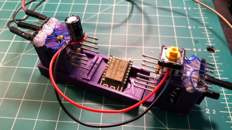
Unfortunately, the ESP8266 form factor isn’t terribly forgiving when it comes time for hooking up a programmer. Rather than having to solder a serial adapter to the chip to flash it, [Ryan] came up with a slick 3D printed programming jig that uses pogo pins. If you have to program these boards in bulk, a jig like this can save a massive amount of time and aggravation.
Beyond the 3D printed holder for the pogo pins, this programmer uses a FTDI USB-to-serial adapter, a couple passive components to smooth out the power going into the chip, and a couple buttons.
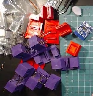
In the video after the break, [Ryan] walks through the many iterations it took to get the 3D printed aspect of the jig worked out. The design went through a few rather large revisions, including one that fundamentally changed the whole form factor. Even with the jig now working, he mentions that he might circle back around and try it from a different angle.
Programming jigs are a staple of electronics manufacturing, and we’ve covered quite a few that have helped transformed a proof of concept into a small scale production runs.


Not to shit on what he has done here — I think this is a good project and could be fun to fiddle with — but just bying a ready-made tool from Chinaman for programming the ESP8266-modules would be cheaper and faster, like e.g. https://www.aliexpress.com/item/ESP-12F-burning-fixture-development-board-ESP8266-without-ESP-12F-module/32812849093.html
Oh, nice!
The material costs to build his jig is cheaper than that fixture, and building it is faster than waiting for the slow boat from china (though does use more of his time, sure).
…but more to the point, just buying a premade solution is not really the spirit of hackaday :P
Not cheaper, or faster. It took me a few days to make this (would take 3-5 weeks to get something from China) and that jig is under $2 to make (ignoring the plastic used in prototypes, might be $5 then). Plus, I got to learn and practice Fusion 360 to do the design which is always a bonus. As a side bonus I can easily print another for myself or for friends or modify/add/change the design to fit certain requirements.
It’s a hack!
Those are nifty pins. Any idea what they are called? would be cool to use in my own jigs.
pogo pins
This was my solution
https://photos.app.goo.gl/iVH8IXtxAHYPMnBq2
that’s nice!, do you load the module sidewyas then lay it flat and let it connect to the other side? i’m not sure how you load the module into the pogo pins
yep sideways, hold the esp8266 at 30 degrees relative to the board and push it towards the pins in until it will fit in the gap.
I’ve planned on building an 8266 programming jig, but this guy definitely beat me to the punch.
I’m pretty sure you could build one much simpler: a basic ‘bed of nails’ pogo pin layout, 3d printed alignment jig, and a soft clamp to push the board in to the pogo pins. No weird vertical holder nor needing pogo pins on both side.
But, again, he beat me to the punch, great to see something working.
I tried the bed, it didn’t work well (for me) so I ended on this design. Size isn’t an issue, it’s a jig so it’s only used for testing/prototyping. This looks complicated but it’s pretty simple, the most time consuming part was soldering the wires.
I build one of these a while back, also on a bed of pogo pins. I found a small amount of epoxy is needed to keep the ponds from wobbling after a few hundred cycles.
https://youtu.be/3vYy9TrM9Js
Design files should be linked in the YouTube description.
You can increase the serial speed of upload to be faster than what you have there. That should save you some time if you are programming multiple boards.
Why not ICP? You lose some pins but gain the ability to reprogram easily.
Unless you want to sell the modules pre-programmed, I agree, it is much more practical to go for the ICP solution. In fact, that is the ideal place to use pogo pins, but much shorter ones, as having that length exposed, makes them prone to bending. Smaller pogo pins are also available, such as the P50-B1 or P50-Q1 (different spring end shape).
I’m not following, could you explain this solution and why it’s better?
Minor type, second line: ESP2866 -> ESP8266. Can’t find a report errors link, so feel free to delete this comment after fixing it :)
Huh. I really like the idea of having pogo pins on both sides of the board. I would have spent a long time cursing, trying to figure out how to get them to work on the 2mm centers…
did something similar to reprogram some smart outlets:
https://hackaday.io/project/20316-wifi-outlet-hacking/log/77082-programming-jig