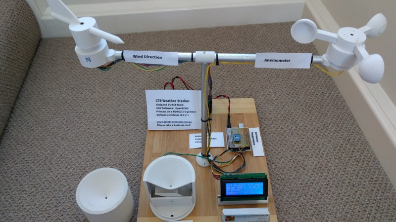
If the term “3D printed weather station” makes you think of a printed enclosure for off-the-shelf sensors, don’t feel bad. We thought the same thing when we first read the message [Rob Ward] sent in about his latest project. Surely he couldn’t mean that he actually printed all the principal parts of a serious weather station setup, such as the wind vane, anemometer, or rain gauge?
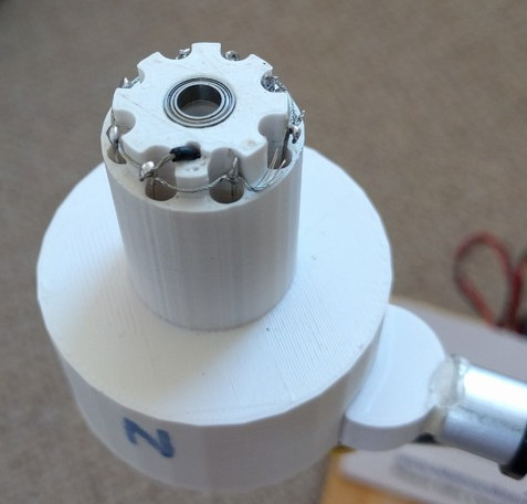 Except, on closer inspection, that’s exactly what he did. Every part of the weather station is designed in OpenSCAD, printed out, and infused with various vitamins to turn them into functional pieces of hardware. Interestingly enough, most of the magic is done with simple reed switches and magnets.
For example, the wind vane uses eight reed switches and an embedded magnet to communicate the current wind direction to the Arduino Uno which handles the user interface. Wind speed, on the other hand, it done with a single reed switch as it just needs to count rotations to calculate speed.
[Rob] did “cheat” by using an off-the-shelf barometric pressure sensor, but we’ll give him a pass for that one. Unless somebody wants to hit the tip line with a design for a printable barometer, we’ll consider this the high water mark in printable weather stations.
This isn’t the first time we’ve seen a DIY anemometer or rain gauge, of varying degrees of complexity. But the clean look of the final version, completely open nature of the OpenSCAD source, and the low part count make this an extremely compelling option for anyone looking to up their home forecasting game.


Neat. Can even add a storm proximity kit that we don’t see common place with the lighting and thunder detectors.
https://hackaday.com/2018/03/28/storm-detector-modules-dancing-in-the-rain/
I forget what age I learned to watch for lightning and listen to thunder to gauge distance along with a wet finger for wind direction. Guessing when I was allowed outside to play as I recall amazing and competing with some with predictions. Would be interesting to see automated.
Far as watching lightning and counting till you heard thunder, for me I was introduced to that method by the movie Poltergeist when it came on cable tv. So around 1983-84.
Neat. My Dad taught me before I can remember clearly and I think goes back to the full time plus farm eras. Relates to playing outside (and to encourage I take my vitamins if I was being to picky eating) and the comments below relating to taking Thiamine for mosquitoes or something like that insect repellent related.
I have combined this chip on a break out board on my 24/7 Oregon Scientific sensor system. However it does provide a lot of information and I have not figured out the challenge of how to represent the data succinctly on my website. Your link though has some handy advice on how to minimise unwanted information reporting. I will look into it.
Awesome, keep us posted. Your system is really impressive and well organized.
You got me thinking also that I have a Lacrosse Technology 9035 here that I was thinking of reading into more and maybe hacking into since the wind related sensor isn’t working at the moment. Last I left off was listening to the wireless signal with an RTL-SDR and Audacity a few years ago. Been busy however with other chores and now getting ready for the warmer weather.
Is it Skywarn training where you can integrate your weather station into the NOAA or National Weather Service network or something like that?
‘vitamins’
SERIOUSLY
It is natural to extend from the biological meaning of “vitamin”–necessary to health and often not produced by the organism itself–to things like magnets and reed switches, which are necessary to the function of the device but are not produced via 3D printing.
Examples of usage:
http://forums.reprap.org/list.php?179
https://www.robotdigg.com/category/10/Maker-Vitamins
I felt flattered anyway, I took it to mean small amounts of good stuff that make a big difference to the health of something.r
I know! I feel the same way! Vitamins by definition have to be organic compounds. What a stupid abuse of language!
Ironically the plastic printed parts are the organic compound in this situation.
B^)
It’s tech jargon. It is arbitrary and borrowed from other parts of language–get used to it. A computer bug is no longer a literal insect, is it? But with that one it actually did start out with a roach stuck in a relay somewhere, so maybe not the best analogy. We call parts of a user interface a window or a desktop. There’s countless weird distortions of words, but like the floppy disk still being a universal symbol for “save” despite not being at all accurate for decades, we don’t notice them when we are used to them.
When you’re building a body, you can synthesize most of your proteins out of amino acids and the stuff you can’t synthesize you have to find elsewhere as vitamins. It’s a useful descriptor for 3d printing.
> “But with that one it actually did start out with a roach stuck in a relay somewhere, so …”
A moth… dammit. Or, is raoch a vitamin-similar analogy to any bug. Wait…! I forget in a bug is an insect.
This is a semi-tech forum. Better we not throw around vagarities. Keep it simple – write simply and accurately. It you are not going to be accurate, it zeems all the more important to be nice. And you can look up where said moth was and its final resting place, yourself.
A moth, not a roach, as [BillSF9c] noted. Also, what Grace Hopper wrote in the log book was “First actual case of bug being found.” The word “bug” had already acquired the meaning of a flaw in circuitry or machinery decades earlier.
Now I must correct my own misinformation as on further reading, it was not Grace Hopper who taped the moth in the log book and wrote the note, rather an anonymous technician.
The design reminds me of microchip’s 1 wire weather station of yore…
One wire weather station?
Around here we call that a lightning rod.
This is awesome. In the past I’ve wanted to setup my own weather station, but was put off by the cost of commercial wind measurement gear. Ended up just doing temp/humidity because the sensors for that are dirt cheap.
With this, looks like I could get some passable (and pretty decent looking, honestly) wind hardware for only a few bucks. Great use of 3D printing.
You really don’t need 3d printing to make something that looks good and works well. I have made anemometers in the past by putting half ping-pong balls or spoons on computer fans with removed blades. The magnet and hall sensor are already there. Granted, on modern ones it’s all in one chip so you might have to use a reed contact in place of the sensor.
I guess our definition of “looks good” is different.
B^)
Beauty is in the eye of the bee holder.
Actually yes, it looks good because it is made of ready made parts that are injection molded, which to me look better than seeing the layers of a 3D printed part.
Not saying the design here is not good looking, just that you don’t necessary need a 3D printer to get good results.
“Looks good” huh? The ol’ built-from-trash aesthetic. It can be alright.
But speaking of looking good, the surface finish on those 3d printed parts is pretty nice. I swapped out a big nozzle for speed prints, but now when I see a proper, accurate, detailed print it makes me jealous. I need to go back to the stock nozzle size.
Thanks Dan, exactly the response I was after. I had thought of making a weather station like this from bits and bobs and I know it can be done, and I could do it, but what makes this approach so special for me is the potential for sharing it successfully with others, and allowing them to improve on the initial design. Now that is what is really awesome…
Anyone know what “LTB” stands for, in his article “LTB Weather Station” ??
Apparently the location it is deployed at (Lake Tyers Beach), from zooming in on the business cards:
http://laketyersbeach.net.au/weather.html
That is correct Dan, well spotted. I use an Arduino with 433MHx Rx to intercept signals from Wind, Rain, Temp/Hum, UV sensors made by Oregon Scientific (no financial connection disclaimer!). this is fed by USB/Serial to a Web Server running a Python program that draws all the graphs and does the logging etc I originally started this project as a way to get traffic onto my site, but over time I have become more and more obsessed with the weather full stop. My 3-D printing project is just an extension of this.
As it is 3D printed, it probably stands for “Long Time Building”.
B^)
using a reed switch to count rotations is gonna fail pretty fast, no? I mean I know they’re rated for lots of repetitions, but the thing will be rotating pretty much constantly
If a reed switch survives ten million clicks, it would fail after about 115 days or rotating once a second.
115 days *of* rotating
f is near r. Some of us are poor typists but hate spell check programs, or at least those on the machine we are temporarily using.
Hall sensor…
How about a optical sensor? Counting light pulses is just as easy.
exactly, harvest parts from a dead mouse.
Ewww!
like the brain, abi normal.
An optical sensor is certainly a very viable option, in fact I have a Climatronics 101990 here on my desk that uses a photo interrupter with a chopper disk that works very well. The down side is the photo interrupter needs to be inside of an IP67 enclosure to keep dirt, dust and moisture off of the sensor.
Might even have guestimate potential relating to a more colormetric horizon indictor to predict.
Yeah, this is the textbook use case for a hall effect sensor. Spinning shaft with a magnet on it? Unless you’re talking about a motorcycle from the 1970s that still uses points, you need a hall sensor.
It might depend on the particular design of the reed switch. I have seen them used in some old car speedometer, where it is detecting the movement of the rotating magnet, making something on the order a couple thousand opens and closes per mile travelled, several hundred millions of these during the lifetime of that car. Then there are the commercial wind sensors (anemometer and direction) that uses reed switches in a manner very similar to the project featured here, which have been spinning in the wind for 6 years and counting, on the roof here. So at least some reed switches are good for a large number of closures.
Reed Switches are very durable if not overloaded with current or voltage, so at the very low currents and voltages used here they will last a very long time. Most importantly for me in this project it allowed a proof of principle for the plastic parts, and allows a wide range of people to access the project. The circuitry is simple and yet works and for many will be more than enough. Sealing the wired/soldered parts off inside the sensor housings would be more important, as corrosion of exposed wires will fail before the sealed switches will. (imho)
The reed switches are very durable. My uncle had an “electric clock” c.1960 that was battery powered. It had an electromagnetic driven pendulum, regulated by a magnet in the base of the pendulum that switched a reed switch that connected a driving coil across a battery. In other words a simple motor. He had the clock running for many, many years, and when I “serviced” it a few years ago it was still working fine. The essence of my project is “keep it as simple as possible to prove it works” and let others refine it if that pleases them.
Having seen and used a number of commercial weather instruments I have to say this is very well done. I have to agree that the only practical way to go for the Barometric Pressure gauge is an off the shelf unit.
I have some suggestions for future improvements:
1.) Instead of the eight reed switches and rotating magnet with all of the associated wiring move to one of these: https://www.usdigital.com/products/encoders/absolute/rotary/shaft/ma3. The Arduino should be able to read the output directly and provide much more granular wind direction.
2.) Substitute a small coil of wire in place of the read switch in the base of the anemometer. As the magnet moves over the coil of wire it will induce a small current that can be amplified and sensed by the Arduino. This removes the life span issue of the reed switches that was mentioned earlier. If you want more granularity in the wind speed measurement simply add more magnets evenly spaced around the rotor which will raise the pulse count per revolution.
3) With more and more folks going to solar power these day a pyranometer would be a hand addition and a basic one can be built from a photocell. With a bit of work you should be able to get a rough approximation of the current irradiance in W/m2 being received from the sun where the observation is being taken.
At $61 for just one of those encoders, the reed switches should be sufficient.
I have built a solar power sensor and given it an Oregon Scientific Tx with the same protocol to run in parallel with the other sensors. It uses a silicon cell from a garden light as the primary sensor, but I am not happy with it as the cell saturates too easily and must try a heavier resistive load. However I also set it up with a 6V solar cell from and a single cell Lipo Cell along with a power manager board from Adafruit. It has been running unattended for the last 8 months, and if I built my own system I would use something like that as the power source and keep all my leads short (see below).
I have used trigonometric tables to do “Circular Averaging” to get finer grain wind direction. Given the wind vane is very light and fluctuates quite frequently it is possible to take a number of readings in a period of time and get the average. Averaging with the speed is also an answer as well. The graphs I have on my site show the average speed and direction of the wind and it is the trends that are observed over time that are more useful rather than instantaneous readings. This is the main criticism I have of the LCD head units that some with the usual low cost “weather stations”, trends are very hard to pick.
Thank you for the compliment ITWxObserver. I did have a brand of BIOS Weather station (before swapping to the Oregon Scientific) that used a 4bit Grey Coded encoded shaft with 4 LED/Sensor combinations to get the 16 directions. It was very well done. However the design of the Anemometer was not up to scratch and I had to junk two of these integrated systems when the Anemometer cups broke off. Hence the change of brands (plus it was no longer made, another impetus to design my own). This maybe why my design here has such sturdy arms connecting the anemometer cups? We may have thrown out the challenge for someone to 3-D print a barometer system :-) At least on my other 24/7 system that part can be indoors, or at least well sheltered, and does not have to be as weather proof as the other sensors.
Well… I have an idea, but most of the parts are not 3D printed… In times of olde’ a barometer was a J-shaped tube (closed on one end) with mercury in it. If you have a mercury barometer or an aneroid barometer, you could couple those with either optical switches similar to above, or use an image processing trick to read the level or needle to generate the number. Since barometric pressure typically does not change FAST, a few images processed a minute would likely suffice. As a note, I once read of someone digitizing a high pressure hydraulic gauge that way — high pressure digital fluid gauges are $$$$$. My bet for the safest, cheapest, and easiest way to build you own barometer would be to read up on how old aircraft altimeters were made and see if you can 3D print a modification of one of them and figure a way to digitize the result. After thinking about it a bit, if you designed a balanced disk with a sweeping triangular cutout, you might be able to pick that up with a capacitance device and read it directly. Other than that I would just use computer vision to detect the position of the needle and map to a number… Hope this helps. If you build it drop me a line ;-)
In reading the original article I don’t see any mention of a solar radiation shield, one of those items that’s always way over priced in the commercial world. Adding humidity to the temperature sensor is super simple with one of these: https://www.sensirion.com/en/environmental-sensors/humidity-sensors/pintype-digital-humidity-sensors/ or one if it’s lower priced cousins. These sensors have the bonus of traceable calibration.
If this can approach the reliability and accuracy of a $1K Davis station, I’m all for it!
From a mechanical standpoint the reliability of this project looks to be rock solid. However from an electrical standpoint when you place an anemometer with eleven conductors 10 meters (WMO standard height) in the air on a tower you have to be concerned about induced voltage from nearby lightning strikes. With that in mind there needs to be some sort of transient voltage suppression added to all of the Arduino inputs with proper grounding.
I see a lot of accuracy and calibration issues with this project:
1.) You have to ask yourself if your looking for a good idea of what’s going on outside or research grade data that has traceability to a known standard.
2.) I don’t see where he mentions taking into account things like “Damping ratio”, “Delay distance”, “Distance constant”, “Time constant” and “Starting threshold” in the design to name just a few factors that will impact accuracy.
3.) The anemometer would need to be calibrated in a wind tunnel to determine its linearity and range. I think the arms will need to be changed from a 3D printed square to a much smaller round metal rod otherwise the airflow will likely be disrupted.
4.) The internal working of the rain gauge look awesome however without raised sides above the collection area in a moderate wind some of the falling rain will end up blown off over the sides instead of entering the hole and being caught by the tipping bucket. Without bird spikes around the perimeter of the rain gauge “stuff” can end up in the hole leading to the tipping bucket.
5.) The temperature sensor is missing any type of solar radiation shield. This should be an easy 3D printing job.
6.) Likewise the Barometric pressure sensor isn’t in any type of enclosure. This isn’t as easy as it sounds when you take into account the Bernoulli Effect will have on the observed Barometric pressure as wind moves around the enclosure.
This is a great project to look over so you can have a better understanding of what goes into a $1k to $10k+ (US) commercially built weather station.
3D printed wind vane and anemometer,
yet another couple of uses for fidget spinner bearings!
You do realize, fidget spinners use standard roller skate/blade bearings that have been around forever….
You do realize that fidget spinners are now passe’ and therefore heavily discounted….
And still more expensive than raw bearings and those bearings in spinners typicaly are very loose to allow for longer spinning times. Some are so loose that you can see their slack.
speaking of fidget spinners and bearings, I’m sitting here twiddling a 3D printed bearing while I read.
If you looking to get a decent starting threshold, say around 1 m s of wind speed, then skimping on the bearings in a project like this is very short sighted.
The little bearings I chose would mean a really tiny hamster sized skate board (hehe 8mm OD). Being able to source these little bearings on E-Bay was a real winner. Finding the light weight brass tubing in a section of scrapped car antenna that fitted the 5mm ID was even more satisfying.
Really nice. If you want historical data and web visualization, you might try weewx on a raspberry pi (or other cheap linux box)
Not a fan of the magnetic sensors at all. I would be afraid of them causing forces on the rotation of the devices. I used optical IR LED optical switches for an anemometer built in college.
Every decent commercial weather station I’ve seen (Davis for example) uses magnet, not with reed switches but with electronic compas or hall sensor. Probably because that solution is more dust resistant than optical version. And is easier to pot into epoxy or some other coating that protects them against elements. You can easily put few milimeters of epoxy above electronic compas chip and still have excellent performance with magnet rotating 5-10mm away.
It would seem that the new batch of HaD readers can’t read a data sheet, or perhaps don’t know how to find one. A reed switch is ideal for this application for at least two reasons:
1 It needs no power, unlike a Hall sensor or optical sensor.
2 The lifetime of a reed switch (when used with such small voltages and currents as in this project) is hundreds of millions to low billions of operations. A billion counts, at one per second, equates to about 32 years.
And for the guy who is afraid of the magnets causing drag on the devices, don’t give up your day job. Unless it’s electronic design or something technical.
Rather or not reed switches are the optimal component for this application depends somewhat on your sighting requirements. If we assume WMO standards which places the anemometer at 10 meters and the temperature and humidity sensor at 2 meters above the surrounding ground we have to deal with several issues:
1.) With the nine reed switches as designed you need eleven conductors in the UV resistant cable between the anemometer and the controller along with ten voltage surge suppressors and grounding to protect the Arduino inputs. With either a US Digital MA3 or 10k continuous rotation pot you only need five conductors and four transient voltage suppressors. The 10k pot costs a bit more then the reed switches however provides better accuracy. The downside of the 10k pot is you need an accurate excitation voltage.
2.) Using a reed switch for the wind speed will require debouncing of the switch closures and I’m not sure how well that will work at high wind speeds over a 10 meter or longer cable. I suggest replacing the reed switch with a small coil of wire where a small voltage will be induced as the magnet passes over it. This solution doesn’t require and debouncing and still doesn’t require any power.
Generally, reed switches don’t need debouncing, but it is trivially easy in software. You can also build a resistor network to convert the output of the eight direction switches into a single analogue voltage. And if you locate the Arduino next to the sensor you don’t need a long wire or lightning protection. Send the data back over radio, wifi, or fibre optic.
The resister network is an excellent idea to reduce the conductor count between the wind direction instrument and controller and super easy to decode in software. If you made the total resistance 10k and had the appropriate values in between you could make it so a 10k continuous rotation pot could be used on an upgraded version without any software changes.
Could the 8 Switches be used to produce 16 directions with that system? That is if two adjacent switches are on would you need an 8 bit binary weighted resistor ladder to resolve it?
For data mining, 16 directions seems fine. But when I want to get a sense of the weatber outside, I have found that the way an analog needle bounces back and forth tell me volumes. How to readily implement this.I am unsure. A lightweight disc w optical slots perhaps… maybe an inner and outer set which being offset slightly, allow mor graularity… and softeware to determin direction change so a hundred optos are not reauired.
I don’t know, but I think so. I have one of the “Fine Offset” brand wind vanes (from Maplin) so I will test it next month. Or you can Google for further information on the Fine Offset sensors.
Rather than using switches and various mechanical components for the anemometer, why not a series of 3 microphones arranged in a triangular formation. A bit of maths and some frequency filtering, you’ll have a true solid state device.
That’s here: https://soldernerd.com/2014/11/14/arduino-ultrasonic-anemometer-part-1-getting-started/ or here: http://embedded-lab.com/blog/making-an-ultrasonic-anemometer/.
Sonic anemometers have the advantage of being all solid state, so no moving parts. They can also be heated so they won’t ice up in colder environments.
I’ve gotten several high end commercial ones off of eBay for under $100(US) a piece. Some even have built in temperature and humidity sensors. Some commercial ultrasonic anemometers use three transducers and others use four. The very best sonic anemometers are three dimensional which allows you to measure both the horizontal and vertical components of the wind movement, quit handy in mountainous areas.
If you’re in need of something really robust take a pitot tube from an aircraft, add a tail to it and mount the assembly on a bearing mechanism so it will vain into the wind. The pitot tube doesn’t care if its moving through the air or the air is moving around it, it’s all the same calculations to determine wind speed. Direction can be determined by any of the methods talked about in this blog post.
Wondering about how accurate the Ardupilot ArduplaneTube Air Speed Meter Airspeed Gauge for APM 2.5 2.6 are. They’re about ~$22 a piece though x2-3 times smaller in diameter so may not be as accurate I’m guessing.
Check out 3D-PAWS (3D-Printed Automatic WeatherStation) initiative that has been launched by the University Corporation for Atmospheric Research (UCAR) and the US National Weather Service International Activities Office (NWS IAO), with support from the USAID Office of U.S. Foreign Disaster Assistance (OFDA).
SEE https://sites.google.com/ucar.edu/3dpaws/
I too have long hungered for a $600 Davis on a 60$ budget.
Still, it lacks one thing important to a gardener; sun/solar quotient. In my chhood.I saw a cloud detector that was simple and cute. 2 small domes, each with a solar ell under. One dome had a checkerboard of black paint.of perhaps a dozen squares. The other dome was painted where the first was not. Any difference in outputs indicated a cloud.
Anyway, solar amount by the minute, if you please, for some of us who visit the outdoors to remind ourselves of how nice it is, inside… but because we were unaware that the outdoors took a brief turn for the better. Yes, cleani g now and again, perfect accurracy not required… Later perhaps alarms for high or low anything. And eventually, like a heater thermostat, both a daytime and nighttime alarm/limit setting. I’d suggest a car ride to test the things durability at 85 or 110, the ratings of common (5-nail,) or better (6-nail, heavier,) shingles.
What of a simple auto MAP sensor for windspeed so that more resources can be put on direction and “direction variance.” ??? Oh yes, the semi-critical power supply… I’m not a great help – so glad many are interested and certaintly a worthy effort is shown!
I was wondering what the specifications are for the MAP and other COTS, not used for weather stations from my observation, airflow sensors.
Reminds me of Design of Experiments (D.O.E.), i.e. initially I want to test for every point I can throughout the range when in reality I can gain enough information from less test points strategically logically distributed throughout the range. Ah… memories of SRM 1920a. 2035 and 2036.
https://www.isixsigma.com/tools-templates/design-of-experiments-doe/design-experiments-%E2%90%93-primer/