Driving a brushless motor requires a particular sequence. For the best result, you need to close the loop so your circuit can apply the right sequence at the right time. You can figure out the timing using a somewhat complex circuit and monitoring the electrical behavior of the motor coils. Or you can use sensors to detect the motor’s position. Many motors have the sensors built in and [Electronoobs] shows how to drive one of these motors in a recent video that you can watch below. If you want to know about using the motor’s coils as sensors, he did a video on that topic, earlier.
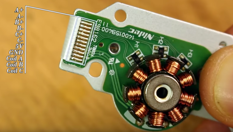
The motor in question was pulled from an optical drive and has three hall effect sensors onboard. Having these sensors simplifies the drive electronics considerably.
Normal motors with sensors have conditioned sensor outputs, but since this was a dumpster raid part, the hall-effect sensors needed some circuitry to drive and read them. A simple LM324 comparator and a few resistors took care of that.
The drive circuitry is just a few MOSFETs that form three H-bridge circuits. The trick is how to sequence the coils so that you get the rotation you desire. The video has some very good animations that explain the sequence and the critical timing involved.
If you decide to duplicate the circuit, note that the video has some diodes backward. You can find an updated schematic on the associated web site.
If you don’t have a brushless DC motor handy, you can always build your own from junk. If you have a 3D printer, you can build an even better one.


Nice thing about BDLC, despite the complexity is the wide availability of ICs to do the hard work. Even the H-bridge isn’t that hard.
https://www.digikey.com/en/articles/techzone/2013/mar/an-introduction-to-brushless-dc-motor-control
Being teased by the title, I was a bit disappointed when I found out it was about a motor already containing sensors.
So what to do if you’d were to drive a motor without sensors ?
This isn’t too difficult … but becomes a real timing challenge. Rather than 3 digital inputs for the hall sensors you need 3 analog inputs on your microcontroller. These analog inputs just monitor the voltage (back emf) on the one phase that isn’t being powered. You basically look for the voltage zero crossing and use that to get prepared for the next phase.
There are some decent videos that can be found online.
Yeah, I believe that this Electronoobs fellow actually built a sensorless ESC driver in a previous video.
Just bought the t-shirt.
Thanks for hinting, anyways :)
Electronoobs is the name of the youtube guy in this Hackaday post, I wasn’t meaning to imply anything. :)
You could always place the sensores yourself. If the motor has 9 poles you will have to place them 360°/9 so 40 degrees one to each other. the rest of the amplification circuit is the same.
But any dead hard drive or vintage cd/dvd drive will have a motor with those sensors; heck there’s even an indian youtube guy that made even a simpler circuit with just 3 mosfets, 3 resistors, 6 diodes and a pot to control the speed.
Next level, use the em feedback from the motor winding to replace the hall effect sensors…
Running sensorless has drawbacks however like jerky and less torque at low rpm. Also if you want a very high efficiency control scheme you need to preserve the back EMF in the coils when they are not powered i.e. if you want a 98% efficient controller, you need hall effect sensors.
I can understand the control issues (jerkiness). But what do you mean with “preserve the EMF”? The comparator circuit for the back EMF usually has quite high impedance, so does not consume significant power. How does it reduce your efficiency?
Tore Lund is assuming huntdesigns is talking about a sensorless setup. When the ESC does not know the position at all (sensorless) it will simply output a fixed frequency. If the motor is loaded so that it’s not rotating at a matching RPM, the timing is all messed up.
But that’s not what huntdesigns was not talking about. The position can be sensed by lookign at the back EMF so the timing can be perfect. This setup is just as efficient as a hall effect sensor setup.
This kind of setup is done in the previous video and referenced a couple times in this video.
.. like the previous video he referenced a few times?