The old maxim is that if you pay peanuts, you get a monkey. That’s no longer true, though: devices like the Raspberry Pi W have shown that a $10 device can be remarkably powerful if it is well designed. You might not appreciate how clever this design is sometimes, but this great analysis of the antenna of the Pi W by [Carl Turner, Senior RF Engineer at Laird Technology] might help remind you.
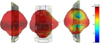
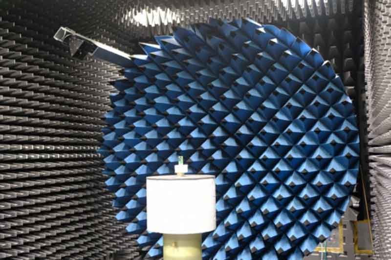
[Carl] used some fancy toys in his analysis, such as the awesome-looking antenna test chamber that his employer uses to test designs. He used this to measure two very interesting things; the radiation pattern of the antenna, and the efficiency. Simply put, the efficiency is a measure of how much of the energy you push into an antenna is emitted as RF radiation. There is always a little loss, but he found that the Pi W antenna has decent efficiency, with -3.5 dB losses at WiFi frequencies. That’s nowhere near as good as the stand-up antennas on your wireless router, but remember that the WiFi antenna on the Pi W is tiny compared to them: it is a small spot on the PCB made by removing several layers of copper, creating what engineers call a resonant chamber. That makes it a remarkable bit of engineering, keeping the cost down and using the copper layers that are already on the board to create the antenna rather than adding a new component.

The radiation pattern of the Pi W is also interesting. Because the antenna is located right on the PCB next to the HDMI and USB ports, you might expect that the signal would be much stronger in some directions than others. And you would be right: it seems that the metal shields of the two ports do block some of the radiated signals. However, it is worth remembering that WiFi signals also bounce around a lot, and other factors can influence how strong a connection is.
The final words of the analysis by [Carl] should be something that all hackers remember:
You can always learn things from clever designs and smart engineers. The amount of effort and creativity that has gone into this $10 computer is impressive—and the results speak for themselves.


But how does it perform compared to the most used PCB pattern (PIFA) ? This is the real question, should we use this instead of PIFA ?
The other issue with using this new one is, I believe, because it is covered by patents (they licensed it from ‘Proant’). So, unless it was significantly better, I wouldn’t expect to see it appearing in many devices because the inverted-F style is free which would be chosen over something that costs.
It’s impressive but for me even more impressive are multi-band mobile phone antennas made just of properly cut and placed copper foil. In 4G phone you have 4-5 of them glued here and there and this is really low-cost solution reached with bunch of engineering.
The antennas are inlaid into the internal structural frame of Sony’s Z3 compact.
And that’s a example I know of from experience.
It is clear that the engineers here did their homework, in this case simulations of the design before manufacturing.
They wouldn’t only rely on simulations, they’d have gone through many prototypes of the systems.
Yep, good designed RF technology is about a lot of simulations, prototypes and some black magic.
Actually RF engineering is one of the few fields where we can simulate so incredibly accurately that if you need to go through more than one prototype then you didn’t do your simulation very well. The maths behind it while complex to solve by hand is actually incredibly simple and straight forward to implement in software. It’s also one of the reasons why there is a myriad of different antenna designs to chose from, there’s very little R&D waste.
“Actually RF engineering is one of the few fields where we can simulate so incredibly accurately that if you need to go through more than one prototype then you didn’t do your simulation very well.”
As a 32-year-career RF engineer who has designed antennas from HF to 160 GHz, I say: NONSENSE. You don’t always have the ability to simulate everything. You don’t always have the parameters of the materials or devices placed around your antenna. Of course you simulate all you can, but you always, ALWAYS back up simulation with prototypes.
I’d not even hire an RF engineer that made the statement that you made.
Right? The “iPhone Antennagate Scandal” alone defends your statement.
I can only imagine the fun with modeling the iterations of permutation and combination effects… especially with materials that don’t have detailed enough properties broad ranges specified. Then there is potential batch to batch variation if quality testing isn’t as rigid when there are more detailed specs and higher standards.
Don’t see how your claim is incompatible with the other one – if the materials used are well known. But then I known nothing about antennas or RF stuff.
Yeah, I’m gonna say +1 on no-hire. Sorry, man, been around the block with EM software enough and engineers who depended too heavily on it to buy the “incredibly accurately” line. There’s always some factor you either haven’t or can’t account for.
This my sound somewhat stupid,can I buy this device to plug into my tv, and say goodbye to cable payments?
You can use a Pi as a HTPC, but a full Pi 3+ would be better and still reasonably cheap.
Most manufactures still recommend a matching network for their antennas, but some modern chips can have the equivalent tuning functionality built into output sections. I am really impressed how far the tech has progressed in the past few years, as FR4 PCB is still unreliable to work with over 2cm^2 at above 1GHz.
Most people still tune their designs low on purpose, and manually ablate off the copper until the boards from a specific supply source are in tune (a few versions are to be expected). There are several things that can pull a design out of spec, as even the plastic enclosure can shift the tuning. ;-)
This my sound somewhat stupid,can I buy this device to cure cancer?
Maybe if it helps you believe you can survive. Survival requires one major requirement… not die. So do whatever you can to stay alive and have a positive mental attitude critically thinking what is happening so you’re not seduced and coerced into being poisoned more since health care can be really corrupt. The Pi is more of a device to keep you busy if you’re stressing I think though there may be Rife Frequencies or even positive sounds that will help the EEG’s I’m guessing. Check your hygiene (try using cleaners that are natural like vinegar, alcohol, iodine etc.), water, agriculture products for food and drug use so there isn’t any toxic sources. Maybe a Pi reminder tool to eat healthy and clean healthy also since concentrated detergents and cleaners can be nasty also. I’ve read poor diet is the number one causation for the elders getting diseases and dying. So a calendar from a Pi or computer to remind you of task to do or even a paper based system is a great idea.
The benefits of a cool job!
Antennae design is a black art, lost on mere mortals like me.
there is no black magic just good engineering
The swedish electronics newspaper ETN had an article about the Proant design a while back:
etn.se/index.php/nyheter/63274-ny-umeaantenn-i-senaste-raspberrykortet
(sorry, article is in swedish)
Also, the Pi 3B+ features a Proant design for dual-band, 2.4 and 5GHz.
It would be interesting to see a side-by-side similar analysis for the dual-band design; does the 5GHz support incur any performance degradation in the 2.4G band?
So the antenna structure appears to be part of the main PCB. Does this mean the RPi Foundation must go through great pains to make sure the PCB material’s electromagnetic characteristics are consistent between not only different production runs, but different production runs by different manufacturers? If not, then the production boards may not meet type-acceptance by the (e.g.) FCC – and keep in-mind it seems they are manufacturing these things in both the UK and China. To avoid this problem, many manufacturers use pre-type-accepted “RF modules” with antennas. But maybe the RP Foundation’s quality control and high production volumes allow them to use this approach in a low risk/cost-effective way compared with using third-party RF “modules”.
What makes this different from the etched squiggle on the ESP8266-1 series? I have not seen an RPI in the flesh in a long time. Somehow the prices that I can get them for always seem to be 3-5X what they claim to be selling them for. Plus the cost of shipping. In fact a quick look at ebay shows them from between $25 and $49. Still not seeing the $5 and $10 boards.
Less pcb real-estate. You are likely not seeing it on $5. or $10 boards other than the Raspberry PI Zero W because the people who generate the other lower cost boards find that the extra board space is less expensive then licensing the resonant cavity. Use of this particular kind of antenna was pretty much a no brainer for the rpi people because it allowed them to cram WiFi and Bluetooth onto the form factor of the pi zero. The “squiggle” likely would have taken up too much space. Besides, I find it much more elegant.
It would be intersting to see a similar analysis of the little metal box antenna on some of the new esp32 boards, like the TTGO.