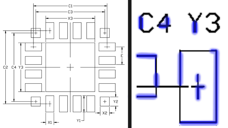
[Conor Patrick] is no stranger to hardware development, and he’s had an interesting project for the past few months. He’s attempting to create a tool to convert images of technical drawings (such as footprints for electronic components) into digital formats that can be imported into other tools. This could automate turning a typical footprint drawing like the one shown into an actual part definition in a CAD program, which could really speed up the creation of custom parts.
Key to the entire concept is the detection of lines in a black-and-white technical drawing. To some people this won’t sound like a particularly challenging problem; choose one or another baked-in line detection function, maybe with a bit of pre or post-processing, and that should be that. It turns out that detecting lines can be harder than expected, and as usual the devil is in the detail.
When [Conor] tried some existing methods for detecting lines, the results appeared good at first but came up short in frustrating ways. Software did not appreciate that in a technical drawing, a line is a single unbroken unit from point A to point B. Without that assumption, what should be a single line sometimes had sections missing, or single lines were detected as multiple segments instead of a unit. Lines that crossed other lines complicated things. Unwanted lines like a “1” or the lower half of a “Y” were being detected. There had to be a better way.
In the end, a custom solution that took proper advantage of the nature of the source images and made the correct assumptions is what made all the difference. With some intelligent threshold setting combined with looking at vertical and horizontal line instances separately, it was possible to locate lines and their lengths far more accurately than any other method he had tried. The system doesn’t handle sloped lines yet, but it might be possible to simply iterate through rotations of the image while applying the same method. If you have a better solution, [Conor] wants to hear from you.
Of course, garbage in means garbage out and sadly not all technical drawings measure up.


The best kind of problem is the one that never has to rise in the first place.
Try using the Hough transform. It works really well, especially in things that are not necessarily rectilinear.
Read the linked article, he tried that, too many false positives for his liking.
For a more general solution, look at the Hough transform and the RANSAC algorithm(with a total least squares regression so it will work for lines in any orientation).
I hate to be that guy but it has no sense to me.
For standard components or derivatives you have free ultra-librarian from manufacturer.
With exotic one, any cad program, because no one guarantee component tech drawing to be accurate and in scale. That’s what dimensions are for. If you do it purely from image, without number checking – you will gonna have a bad day when pcb arrive.
Agreed. Since the datasheet has the dimensions and general package description, a ( flexible, extensible ) parametric generator seems to be more useful.
Choose the tipe of package ( TSOP, for example ) , number of pins, dimensions of necessary pads, etc, then the program would generate the desired footprint in svg or whatever format the software can accept.
Yes basing a footprint just on image scale would be problematic. Many footprint drawings have dimensions and those can be recognized in the image as well. Won’t be 100%, but a lot of info can be accurately pulled from image. Pads, symmetries, pitch, etc. That information can then seed a parametric generator and any missing info can be filled in.
I agree. The image sets you up for a horrible day
It’s very common to have engineers just to put the dimension table on the change order as it’s way faster. I certainly would just update the table if the picture looks pretty close, and I would advise others to.
Don’t worry, you aren’t the only “that guy” on this topic. I was thinking the exact same thing. Maybe this is more of a need for the ow end design packages? I have never needed to do this with DipTrace or Altium.
I think the real problem here is defining the solution to the problem. I think he should be subtractively be seeking text, arrows, lines forming the largest polygons, and all remaining lines.
However, I also think that datasheets should have information about the parts (like dimensions) encoded in the PDF.
Most modern datasheets have the drawings as vector graphics already in the PDF, so perhaps it could be easier to process the vector information instead of trying to recognize lines from a bitmap.
Not to distract from this interesting project, but yeah. It’s trivial to load a PDF in Inkscape or Illustrator, and copy out the good bits. Occasionally a manufacturer will populate their datasheet with bitmap graphics, but that’s the odd exception.
After reading with attention his blog post, it seems he is not going for the dimensions, but just for the representation of the lines/rectangles/arrangement of pads.
As a study of the techniques of line recognizing, as it seems, or as a demonstration on the results of such techniques or their implementation, versus just using some boxed code by other where you do not know what it does, it seems very good and interesting ( also on the description of the math used ) .
Maybe not useful ( or even intended ) as a way to create component footprints, as it would still need a lot of human comprehension to enter the correct dimensions and relationships. As a tool for creating the bare layout of the pads it is also just “interesting”, but not that useful. A better result will be given by some tool that asks the dimensions and draw the footprint based on that.
What I was thinking was using the information that can be accurately gleamed from the image to populate some graphical parametric footprint generator. Any additional info can be added or edited after the image conversion.
Check out my open source software https://github.com/J-east/JevonsCameraViewer makes it really easy to tune machine vision parameters.
Interesting problem! I know Adobe Illustrator does an ok job detecting lines in its bitmap to vector conversion, but the next step is finding the squares and convert them to footprints, at least that’s how I take it, that that’s what you’re after.
I think I would scan the image and find all the T and corner sections, then find all corners that point in a square fashion (you can try interpreting the T sections, ignoring ‘dead ends’ which terminate in a non closing shape/open line). Something like start at a corner, then detect which way the line goes up/down/left/right. Count the number of pixels going in the same direction, record the coordinates of the corners. A corner resets the length counter, a dead end will ignore and retrace in case of a T split. When four left turns are detected with x lengths and y lengths equal, you have a square/rectangle.
If some user interaction is possible, the user could indicate pin 1, then use a strategy to number the pads.
Sloped lines can do the same, instead of detecting in a + pattern, use a circular pattern. The angle and distance can be detected. Start with a small circle around the starting point, then start increasing the radius of the circle and find continuous lines, if the line changes direction, use that position as the new corner and start a new radius of a circle.
Detecting line thickness would be essential, simply follow the outer edge of a line, then use + or o pattern to detect what angle the line is at, then detect perpendicular to the line to detect the stroke thickness. The thickness should remain constant within a certain degree and use a threshold to detect crossing lines and perhaps filter with the crossing line detection which could be done as a preprocessing step.
Store/mark each detected pixel location, add the pixels with the stroke thickness. Test each pixel if it was already detected, rinse and repeat.
This way you could detect primitives like squares, rectangles, triangles and circles.
If you have an OCR module/library, you could use it to mark text regions, which will be excluded when detecting lines. Alternatively, you could also manually mark regions to be excluded.
Just my 2 cents worth.
The generically named PCB Libraries software actually does a pretty good job of parametric part generation. You can even generate STEP models from the part if you need them. I think they just made the Pro version free and they are working on a schematic symbol generator as well.
https://www.pcblibraries.com/
Start with corners? I know opencv has a corner detection feature to find corners then maybe connect corners by searching for paths of black pixels between them?