
I’m in the planning stages of a side project for Hackaday right now. It’s nothing too impressive, but this is a project that will involve a lot of electromechanical parts. This project is going to need a lot of panel mount 1/8″ jacks and sockets, vertical mount DIN 5 connectors, pots, switches, and other carefully crafted bits of metal. Mouser and Digikey are great for nearly every other type of electrical component, but when it comes to these sorts of electromechanical components, your best move is usually to look at AliExpress or DealExtreme, finding something close to what you need, and buying a few hundred. Is this the best move for a manufacturable product? No, but we’re only building a few hundred of these things.
I have been browsing my usual Internet haunts in the search for the right bits of stamped brass and injection molded plastic for this project, and have come to a remarkable conclusion. Engineers, apparently, have no idea how to dimension drawings. Drafting has been a core competency for engineers from the dawn of time until AutoCAD was invented, and now we’re finally reaping the reward: It’s now rare to find a usable dimensioned drawing on the Internet.
This post is going to be half rant, half explanation of what is wrong with a few of the dimensioned drawings I’ve found recently. Consider this an example of what not to do. There is no reason for the state of engineering drawing to be this bad.
Example One: It Gets Worse The More You Look At It
This first example comes from Bitches Love My Switches, an unfortunately-named storefront, but one that does have a lot of neat switches and jacks with a warehouse on the East Coast with quick shipping. If you want some jellybean parts for guitar pedals and associated audiophilia, it’s a nice place to know. This store doesn’t manufacture their own switches, and with that comes the problem of datasheets and dimension drawings. These drawings were made by a random engineer somewhere, and this person has no training in dimensioned drawings.
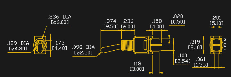
 Let’s work through a design problem using the dimension drawing shown above. This is a PCB-mounted, switch, that is meant to have a nut holding it down to a panel. Think of it as a PCB standoff, only it’s a switch. This switch can be used as a mechanical, structural part of an enclosure.
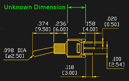
To design anything using this switch, you need to know the height of every part of this switch, from where it attaches to the PCB, to where the nut will screw on. You need to know the height of the switch body. This dimension is completely absent in this drawing, making the drawing absolutely useless. The dimension you need to design anything using this switch is absent. But this drawing gets worse.
What if you wanted to know the height of the ‘toggle’ that physically moves in this switch. It’s labeled in the drawing as 9.5 mm, but this dimension is useless at best, and wrong with even the most liberal interpretation. Why? Because the toggle pivots. The tip of this toggle moves in an arc, and the tip will be ‘longer’ in the middle of its swing than it is in either of its latched positions. A real dimensioned drawing would include the 9.5 mm dimension and the angle of the toggle in the latched position so you can figure out the actual maximum height of the switch.
Want to hate this drawing even more? Sure thing. What sized nut goes on the threaded portion? Exactly. This isn’t a swing at the store selling these switches, but it is indicative of some terrible practices across the entire electronics industry. Somehow or another, everyone forgot how to create useful dimensioned drawings.
Example Two: All Loudspeaker Manufacturers Meet at Bohemian Grove
The project I’m working on will also need a speaker. The general specs are a 3-4 inch diameter speaker that can handle five Watts. I’m not looking for quality here, but I am looking for something I can design an enclosure for before I order it.
A speaker is a remarkably simple device. There’s a coil and a magnet, two terminals, a paper cone, and a metal flange with four holes around the perimeter of this flange, offset ninety degrees from each other. Nearly every generic loudspeaker will follow this prototype, and if you’re building an enclosure for a speaker, there are really only three things you need to know: the diameter of the hole you need to cut out, the depth of the speaker, and how far apart the screw holes on the flange are. I only need three dimensions here. I’m a simple man. I’m also extremely disappointed.
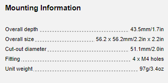
Celestion is a very highly regarded manufacturer of loudspeakers. They’ve been around for ninety years, they created the first metal-dome tweeter, and produce what is said to be the standard in guitar amp speakers. If you’re in the loudspeaker industry, Celestion is where you want to be. Surely they can come up with datasheets and tech specs that would be useful, right? Think again. Their AN2075 loudspeaker lists the overall depth of the speaker, the cut-out diameter, and the overall size of the of the speaker. How far apart are the mounting holes? Screw you, that’s how far apart they are. This isn’t even ‘drafting’ or ‘engineering drawing’. This is just incomplete information.

Celestion is not alone. Take a look at AliExpress. If you’re looking for small, cheap speakers that can handle ten or fifteen Watts, you have thousands of choices. Virtually none of them will have the relevant information on their product pages. Yes, you’ll usually get the dimensions of the flange, and you might get how deep the speaker actually is. You will rarely find where to put the screw holes on your project enclosure.
I’m not one to believe conspiracies. People are just too self-interested to be part of a cabal of evil bent on distorting the truth or ruling people. It’s the media theory of Chomsky versus Žižek; self-interest rules all. People are too stupid to organize. This may be the best evidence yet that conspiracies exist. There must be a conspiracy between loudspeaker manufactures. None of them have dimensions of where the holes should go.
Example Three: Jacks
This project will also make use of DIN 5 connectors (but not as MIDI jacks), and these must be panel mount connectors. Nearly every DIN 5 connector you’ll see on Mouser or Digikey is a right angle connector. That is to say, you solder the connector to the board, and the DIN 5 connector comes out at a right angle to the PCB. This isn’t what I want — I want a connector sticking straight up out of a board. Yes, these connectors exist, but again we’re left with incomplete dimensioned drawings, like the one I found on AliExpress below:
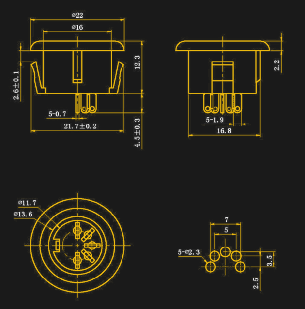
First, take a look at the photograph of the part. It’s what you would expect for a DIN 5 connector. There are five pins, and an additional grounding pin for the shield of the connector, just like every other DIN 5 connector on the planet. Take a look at the drawing. It’s actually not bad, and even gives me a preferred PCB footprint for five of the pins. But what about that grounding pin? It is absent on the dimensioned drawing. If you buy a thousand of these and run them through an assembly line, you’ll quickly find you have to snip off all the grounding pins before populating them into boards. The data is just missing, and you’re a fool if you engineer something directly from the drawings. You should be able to engineer something from the drawings, and this panel mount DIN 5 connector is a terrible product.
Any University That Has Dropped Their Drafting Class Is Doing A Disservice To Their Students
Since time immemorial until the late 90s and early 2000s, engineering drawing and drafting was a required course for all engineers. This is the class with T-squares and triangles and a hidden emphasis on developing fine motor control through lettering. Only a week or two of this class was devoted to dimensioned drawings, but this week is vital to all engineers. Your drawings are useless unless someone else can use them, and you can’t do that without properly dimensioned drawings.
I don’t know why I keep running into truly terrible dimensioned drawings. This is a required skill for all engineers, regardless if they’re educated in China, England, or the US. Yet it’s nonexistent everywhere except for the McMaster Carr catalog.
If you’d like to learn about how to make dimensioned drawings, I’d suggest picking up [French]’s Engineering Drawing. Yes, the book is 100 years old, but what it teaches hasn’t changed in 200 years. This is how the draftsmen for the Apollo Lunar Module learned how to draw. Yes, lettering is hard if you don’t have the right pencils and have underdeveloped fine motor control, but we’re using computers now anyway. Read this book, learn how to properly dimension drawings, and stop annoying engineers who are trying to build stuff.


I do a fair amount of footprints for SMT parts. It’s disgusting how hard it is to figure out where a pin is located without going through a bunch of addition, subtraction, and division. They could have made it SO much simpler by simply adding a couple more dimensions. But no, it’s like programmers that think adding spaces to source code will use up too much of their 80TB SAN box…
The folks who made the drawings for SMT micro-SD card slots are egregious offenders here. You can figure out a footprint, but it’s an unbelievable pain in the ass.
Or sim-card holders. Or anything non-standard made in china. It’s just awful. And then after entering most of dimensions into part generator, everything generated 2.54 times too large. Good thing that I always print my pcbs on paper and try placing components before sending to fab.
that’s a sane practice, i mean the printing out :)
As long as you don’t forget that many printers like to scale by 97% by default, especially laser printers, because the paper can feed in slightly wonky and the printer would risk putting toner where there isn’t paper.
Dax, I have never seen that. All of the printers I have used have been incredibly accurate.
I agree with you. Due to how consistent SMT datasheets don’t give me what I’m looking for it must be part of some standard…
There’s a less conspiratorial reason for the same horribly formatted information on every datasheet: one company designed the part, then everybody else copied it and its drawing. Oh, they may have redrawn the pictures, changed typefaces, moved the tables around and such, but they didn’t rethink anything. If the company that created the original design made obnoxious drawings [glares at Hirose], then that propagates to all the knock-offs.
Entry of one incorrect datum gets propagated to every damn website, and just try getting any of them to correct it.
That happens a lot with automotive products. Just one example is a bundle of vacuum hoses for a 1994 and 1995 Buick Century. Someone, somewhere, incorrectly entered the description as a “wiring harness” and 100% of the new old stock surplus parts sites blindly copied that bad info to their sites. Some may have fixed it because once I finally found the hoses I told the company I ordered from and all the other sites I’d looked at about the error. “Please move part number so and so to VACUUM HOSES so people can find it.”
A good example I remember: the SFP standard (by the open SFFC) specifies the enclosure, module and connector dimensions for gigabit plug-in modules. The _original standard drawings_ omit critical dimensions. So, anyone manufacturing compatible parts has no choice but to use the original drawing and dimensions (or lack thereof).
The exact problem I had: an SMT connector that does not specify pin lengths. Seriously. So I can’t verify the footprint dimensions against (IPC or in-house) recommendations. The only way to read anything useful from the standard must be that they specify _the footprint_, which leaves me at the mercy of the manufacturers, whether they followed IPC (or other) dimensions so as to fit their pins to the footprints properly.
What a cluster.
Another silly example: a Memory Protection Devices CR2012 cell holder datasheet, which specifies no tolerances, other than the general +/- 0.3 mm in the titleblock. If I’m to take this at literal, face value, the footprint is useless: the two alignment pegs on the bottom side have mismatched sizes (to ensure polarity), which are different by less than the tolerance; add in their positional error, and you must make both holes about 0.5mm oversized, defeating the purpose. Fail and a half. As it happens, the real part is within 0.1mm of the drawing, but it sure would’ve been nice to actually know that.
I design circuit boards +1 to the terrible drawings for footprints some data sheets completely lack a drawing of the footprint.
It is much easier to understand a program if you can see more of it at a time, the programmers are not saving drive space but more valuable screen real estate. Imagine trying to program where you are allowed to see only one character at a time, think how much better would it be to see a whole line, more is better.
Can you please come to my office and explain that to my boss?!?!
Other old timers might remember being able to look at an entire program on 14″ green-bar paper from the mainframe’s printer, and how easy it was to mark out the subroutines and loops in your FORTRAN or COBOL programs. Also, flow-charting as a design tool. Now get off my lawn! :-)
I’ll see your chain-printer and raise you 2 1600bpi 9-track tape drives.
Since there’s no “thumbs up” feature all add this “amen brother” comment.
I don’t understand what is so appealing about scrolling through white space.
I also share the frustration of datasheet footprints. Many pads require significant calculations to figure out the dimensions and/or location.
Hmm… seriously, it is really so hard to find out the size and spacing of some pin’s on an SMD part?
And If you really find it difficult, then I suspect that they made is so complicated to separate the amateurs from the more experienced. Because IF things (like electronics) were easy, well, then everybody could do it.
And if everybody could do it, then I (an electronics engineer) would not be special anymore?
Things that seem overly complicated to some are simply complicated for a reason and mostly well understood by others. Don’t put the blame on others if you don’t get it, study a little longer and try to understand why things are done the way the are done. Everything has a reason, even if you don’t see it.
HOWEVER, there will always be datasheets that miss vital information, that are not clear about top- or bottom-view. That do no properly indicate the order numbers… sometimes you need to go through generations of datasheets for a simple LED to find out what the additional characters on the order code exactly mean. A lot of times the device markers are incomplete or not available in the datasheet at all. And sometimes there is just a simple typo which is fixed in the next release of the datasheet but you didn’t download that version…
Let’s face it, shit happens. But most of the time, if you know where to look and what to look out for, it’s a wonderful world.
If you’re worried you would lose your job to someone less educated if footprints in datasheets were any better, you have bigger worries. Being an electrical engineer isn’t about drawing lines on a PCB, or footprints in a library. It’s about understanding requirements, components, parasitic properties, failure modes, understanding when and what you need to simulate or calculate, and just understanding the relevant physics in general. If datasheets had all the relevant information in useful format, you would have more time for the actually difficult aspects of electrical engineering.
I suspect you haven’t made too many footprints. I’ve done it for a living for 20 years and poor dimensioning of parts is a rampant problem with many vendors. Most of the dimensions are done from a “checking” point of view not a creating point of view. To suggest that the data sheets are deliberately complicated is moronic.
We have IPC and other stuff, but power qfn is still mystery for me. Every manufacturer has slightly different name for this package, every manufacturer has slightly different suggested land pattern for this thing and all of the are somehow incomplete.
For example http://ww1.microchip.com/downloads/en/DeviceDoc/20005159B.pdf – paste? who needs paste right (yet you reed in whitepapers elsewhere that if you use paste same size as the main pad, it s too much and the part will float on that).
If somebody has some good source of documentation on this, it would be helpful. I tried http://www.onsemi.com/pub/Collateral/AND9137-D.PDF but not perfect – the parts tend to float to one side (drain) – they work but they are not centered.
The paste issue is complicated by thermal vias. If you have ’em they wick up some solder and fill the hollow core with what amounts to a tin peg (great for wicking heat from the component side to a ground plane on back) but the proper amount of paste with them often will float smaller parts if you don’t have em. (And if you do put thermal vias good luck ever pulling that chip off with a hot air rework station). In an extreme case when the surface area of the center pad approaches or exceeds that of the pads around the edge the part won’t reliably self-center if there’s too much paste under that center pad. Of course too little and the thermal (and for some parts, ground) connection will be lousy and lead to maddening flakiness.
There’s just a lot going on there for a single rule of thumb to cover all parts and all use cases that happen to use that footprint.
I never worry about paste — we use a knowledgeable assembly house that makes their own adjustments, anyway. Example: my layout shows a huge square (exposed pad) of paste; boards come in having been pasted with smaller segments (on the few boards where you can tell, of course — DNP components). I assume (but can’t really tell if) they modify smaller component pads, too.
If you’re doing it for yourself, or you have a less fully-featured assembly house that just uses your data at face value — you’ll have to make these adjustments yourself. That’s a lot of back-and-forth between your assembly results and your footprint library, so you can see why such assemblers exist despite the premium.
I’ve got one for ‘ya, FT232R I think it was. They call it a QFN. I couldn’t make heads or tails of their drawing. It was sloppy to begin with. I made a QFN footprint. Assemblies come in, they soldered alright but the joints look sketchy as fuck: blobby, like the solder didn’t adhere to the pin sides (no toe fillet). On closer inspection, they didn’t, because the pins _don’t wrap around the package_.
Fuckers actually made an LGA. The pins penetrate the bottom surface, and the sides, but not the corners.
With that in mind, rereading the datasheet, it made a little more sense, but not nearly enough for that to be my fault (or my coworkers who reviewed the design).
It’s to the point where, for me, I wish that KiCAD and other ECAD packages came with footprint editors that included 2D parametric dimensioning like the mechanical CAD programs like SolidWorks or even FreeCAD have. The ability to drive dimensions or have a few constraints would go a long way to enabling us to create footprints from the crappy drawings given.
…That or the damn component manufacturers could make their damn footprint drawings in a sane way. I shouldn’t need to use Pythagorean’s theorem or Trigonometry to whip up a quick footprint! Footprint creation always slows down PCB design way more than it should because of sloppy drawings.
I have, more than once, actually drawn a complicated footprint in the Solidworks sketch tool, exported the result to a DXF, and imported that into Eagle. Solidworks has it’s faults (quite a few actually, like the fact that surfaces don’t have a defined top or bottom), but the sketch tool is very good compared to most PCB CAD tools.
I don’t know about Altium though; is that any better?
Nope, Altium is almost as bad as the rest of them.
My father taught me early on to *get all of the parts first* before laying out the PCB. This has saved my ass many times.
And yes, printing out the component gerber layer(s) is *mandatory*.
I’m a mechanical engineering professor and don’t fully understand the content of the drawing, but the only thing I can think about here is the stack-up of tolerances based on the allowable variance of each part. This is where +/- dimensions fall short and you need to use geometric tolerancing – come take my course if you want all of the details! LOL
That’s it! Tolerance! Maybe they don’t document things because if they did you would see their crappy tolerances and complain that the part is not what you ordered!
Or is that what you were saying… I didn’t follow all of it.
If there was a dimension specified for the length of the entire switch (I’m assuming this is example 1 we’re talking about here), then yes. One (the least critical) dimension needs to left blank to leave room for tolerances in all the specified dimensions to stack up. Otherwise the drawing will be “overconstrained”, in parametric CAD terminology.
But since the full length of the switch is unknown, the length of the switch body cannot be calculated.
More projects? You’re as bad as me. Are we ever gonna see that 68k?
Apparently I just do badges now. I did three this year. Next year it’s going to be at least ten.
I’ll do the 68k whenever someone can find me a filing cabinet filled with old Motorola app notes.
Archive.org is your filled cabinet
https://archive.org/details/texts?and%5B%5D=motorola
I _really_ love them
They’re not in the archive.
I have a list of about two dozen 68k-specific app notes. I know the titles. They do not exist anywhere on the Internet.
You know, the easiest way to get correct information or nonexistant documents out of the internet is just to post incorrect information.
I can guarantee that someone has a bookshelf of old motorola binders.
I am guilty of recycling a few shelves because in my niavety I thought it would be better to build a computer out of an 8086 and kept the shelf of intel instead of the motorola.
Now I know just how wrong I was and weekly regret making the uninformed choice on that one; I really hate 64k segments now… so very much…
Do you have a couple of examples you could share? I know a couple of people I could bounce them off …
(In case it’s not obvious, I wanted to give a 68k a shot once I’m finally happy with my z80, and it seemed sensible to let someone else do the legwork first ;)
Post the list as a challenge to HaD readers. If we can’t find them then they don’t exist anywhere, in any form.
“You know, the easiest way to get correct information or nonexistant documents out of the internet is just to post incorrect information.”
Heh, heh, yeah just start talking shit on an Amiga list or forum. For internal behaviour, the technical emulation discussions.
“Doesn’t exist on the net” is sometimes “google can’t find it.” occasionally you break through into a whole nother mini-universe that isn’t well indexed, because it’s all personal and hobbyist pages that don’t use SEO, just have actual facts on them, imagine that.
I have a shelf full of 68k related stuff I got from Motorola back when they would send hard copy bound app notes to you for free via postal mail upon request. It was a dream come true for a geeky high school kid (that Motorola didn’t know wasn’t a professional engineer).
A badge with DIN5 sockets? Nice!
This is my bread and butter, really that fact that most universities have at most 1 or 2 drafting and design classes and most community colleges have a very broad 2 year drafting degree is a shame, let alone dropping it completely. Drafting and design could easily be an entire 4 year degree. I’m not sure anyone is learning the basics of ASME drafting standard especially geometric dimensioning and tolerancing.
Do you think the future might be dropping these parts in a 3D scanner, and supplying these models to customers from which they could measure and generate drawings to their hearts content?
It might be something worth thinking about before creating degree programs for jobs that might not exist in 15 years.
3D scanners will absolutely not fix this problem. These parts already exist in CAD, but the manufacturers don’t share the models, for whatever reason. McMaster makes CAD models available, but they also provide properly dimensioned drawings. Perhaps as 3D printing becomes more and more mainstream, we will start to see CAD models released in lieu of useless drawings, but I won’t hold my breath…
3D scanned model is at best acceptable as a reference, it’s a sample size of one, it doesn’t give us any sort of tolerance information. It’s not about having some dimensions attached to some part, it’s about knowing what the entire set of parts will be, what features are important and others less important and relative to what. There is a ton of information embedded in a dimension and tolerancing scheme, that’s not immediately apparent or would be lost altogether using some basic reference dimensioning.
Excellent idea. As the population average IQ gets lower, 3D scanners are part of the global strategy to face idiocracy. When one cannot depend on his fellows to accomplish correctly the simplest tasks, a 3d scanner runnning TensorFlow might do the trick. Prepare the future… for our kids… and the kids of our kids… while we can…
And yet the intelligence increases.
In my experience, 3d scanners have never yielded a result with any precision. Models created with such generally require huge amounts of hand cleanup to even look vaguely like what was scanned.
Maybe if you spray your part with flat white paint, you might have a chance of getting an intelligible result, but then your dimensions will all be off by the thickness of the paint…
I am learning those things! Except I’m working as a CNC machinist instead of as a designer. It seems that having the head for the one works pretty good for the other.
I suspect there are a handful of other factors to why this is so prevalent (and you are accurate that electronic parts have terrible drawings):
1. EE’s doing mechanical drawings, enough said
2. Paranoia of companies that their design will be stolen if they provide too many dimensions (guess what, they will be stolen regardless – so just provide the dimensions),
3. Parts are designed and manufactured so haphazardly that nobody actually knows what the dimensions are, the finished part gets stuffed into bags and someone in the marketing department creates the datasheet drawing using caliper measurements.
Sometimes the best information wasn’t provided by the manufacturer, but by a third-party that naturally wanted money for it…sometimes lots of money.
0. Why bother?
Yes, apathy on the part of the people selling cheap parts on AliExpress is number zero on my list, too obvious to bother mentioning
It’s the apathy of the manufacturer. People on AliExpress do not manufacture connectors.
4. The plastic extrusion is expected to vary from batch to batch in a certain direction, and the design was optimized to squash the variance into that one dimension. The lack of precise figures for that dimension in the drawing was intended by the engineer to lead you to not rely on it at all.
This is the type of assumption I make when I see drawings like the switch in the picture. It is a panel mount switch, and all the most important dimensions are given; the missing dimension is on the plastic parts; and it is the one dimension that matters least in a panel mount switch. The same switch in a board mount version would have different importance of various dimensions.
I often look at a datasheet and curse the engineer, but also often later after I’ve worked with the product more I start to say, “OOooooohh, that’s what they meant in leaving that out; I’m supposed to calculate from the other side! Probably why I saved 2 cents…”
That can’t be the case, seeing how these switches operate mechanically via a lever ending in a spring-loaded ball against a V-shaped piece of metal pivoting over a fulcrum. If the casing dimension varies too much, the switch fails to operate.
There has to be a more or less exact dimension between the mounting screw where the switch handle pivots, and the inside bottom of the casing. Otherwise the little spring loaded ball falls out of its socket or the switch gets jammed; that’s a frequent failure with these switches when the switch overheats during soldering and the center leg that’s acting as the fulcrum melts free of the plastic and shifts around.
Yeah I think you’re giving the person who did the drawing way too much credit. I doubt that piece is extruded, the parts are all likely injection molded. I think the dimension was just left out because of an honest mistake.
Sometimes on eBay they have very accurate dimensions of the package.. but no dimensions of the product :)
https://i.ebayimg.com/images/g/uxwAAOSw~y9ZDCq8/s-l1600.jpg
That’s so sad it’s funny.
In Ebay’s defense, that’s a soldering iron tip. What next, dimensioning tooth brushes?
Why dimension the box then?
The buyer is hardly interested in the size of the packaging.
Who knows, maybe so a retail store who’s buying bulk stuff can know how much space the packaging will take up. Or it could be to help customers understand the shipping cost. For example if an item looked small but was actually quite large, people might freak out about the shipping cost unless you threw some envelope dimensions letting them know what size it is.
What happens when you have to design an attachment for that toothbrush, or a soldering iron that will hold the tips in question? It’s not very fun to order one of something just to get your own dimensions and HOPE they are all close enough to the size of the random one you got. It’s much better to have the process data available, so that you can design things that will match other things with a given confidence level. Accepting even a small percentage of this low-quality work, means we abandon the standards that make it possible to design this way.
Too late druff… We’ve all accepted it in one area or another. It’s the free shipping (from China) that closes the deal.
Well, I’ve been on the lookout for a shorter length tip for TS-100, because it would make it easier to solder small parts.
Exactly, soldering iron tip dimensions are of great importance.
(If anyone knows where I can buy a shorter T12 / T13 tip, please let me know)
The first one isn’t a PCB mount switch. It’s a panel mount switch. The longer center leg is the tell. That’s a switch you would mount in a panel and solder wires to. So the height of the switch body isn’t that critical. If you look at the PCB mount switches on that site, the height of the body is specified. And if you really need the height of the body for the panel mount switch, well it’s almost certain that the PCB and panel mount switches are identical in that regard.
Of course I’m not saying the panel mount switch shoudn’t have that dimension listed. But you’re ordering from a site called BitchesLoveMySwitches. You think not having all the dimensions is bad? You don’t even know who manufactures that switch, and you have no way of verifying the specs listed are correct. Order your switches from Digikey or Mouser and you will have a full datasheet with all necessary measurements including the thread size.
In all fairness to @Brian Benchoff, although he doesn’t link to a specific part, this PCB-mount switch is accompanied by the same (incorrect) drawing he posted:
https://lovemyswitches.com/taiway-sub-mini-spdt-on-on-switch-pcb-mount-long-shaft/
That is the switch he is referring too. But I take umbrage with your use of the term “incorrect”. Incomplete is a fair term to use. But nothing in that drawing is “incorrect”.
I will not challenge you to a duel. Good day.
The center pin on that drawing is longer than the others. PCB mount switches aren’t made that way, and the photo doesn’t show that. Therefore the drawing is in fact, incorrect.
You’re right about pin length. I stand corrected.
I agree. This particular switch example is weak in this overall thesis. The dimension of the switch length at arc peak is unnecessary because a human finger will need to be able to toggle it, so this requirement demands a depth of at least a human finger. The reason the dimension is given when the switch is activated (down) is because this is the position where it may be covered. It will not be at full height with a cover over it because of the human finger requirement. As for the screw holes in speaker flanges not being documented, this is pretty much industry standard. Some speakers will have a template that ships with them and I suppose this could be included as a downloadable data sheet. But really, speaker manufacturers are shipping their product with the expectation the installer will drill a hole as necessary for proper fitment.
The missing dimension is the height of the body of the switch, not the length of the bat. And that matters for a PCB mount switch when it is also designed to be attached to a front panel. If you don’t know the body length then you can’t tell how long the spacers for your PCB will need to be or if the PCB is mounted to the bottom /back of the enclosure, how far that needs to be from the front panel.
The author seems to think the length of the bat is essential– “Why? Because the toggle pivots. The tip of this toggle moves in an arc, and the tip will be ‘longer’ in the middle of its swing than it is in either of its latched positions. A real dimensioned drawing would include the 9.5 mm dimension and the angle of the toggle in the latched position so you can figure out the actual maximum height of the switch.”
My observation is that the peak of the arc measurement is moot as it requires a finger to move it into that position, so the space will need to be infinitely variable.
What if I want something to retain the switch in either position? (one of those flip up “missile switch” covers or similar)
No angle is specified, no distance from the centreline, so I can’t do that.
I agree, it’s not a very important dimension for 99% of uses, but it might be useful to someone.
The overall length would be more important in a 3-position switch, but I’m not motivated enough to check if they’re dimensioned any better :)
Not an excuse to not include a fundamental dimension. Maybe it’s acceptable if you will mount only one speaker, but not if you are purchasing hundreds. You can´t halt the design of the enclosure waiting to receive the speakers. You need to know all relevant dimensions before deciding what speaker you will use.
This is not only an electronic parts problem. All parts industries are the same. The production drawings are usually very good (I’m a mould designer). But the drawings for the datasheet are handled to some intern or some “technical documentation writer”, and not supervised.
Of course, if you are going to buy hundreds or thousands of the same part from a legit source, you need only to ask, and will receive even surface finishing specifications. Maybe you will receive production drawings for the part.
I had the same thought you did, and was ready to rip into @Brian Benchoff for his deplorable ignorance of human factors. But then I thought for one second more, and realized that many toggle switches have a center detent where the bat stands vertical; that BLMS sells this type of switch, in On-Off-On and On-On-On(?) variants; and that @Brian might even be using this switch type, where total bat length is critical for dimensioning any kind of panel cover.
It’s not a human factors decision. That dimension doesn’t make any sense on its own. The switch moves. Why write down its length when it’s at its shortest, when you can’t tell what it is at its longest?
It’s a superfluous dimension in the absence of *another* dimension, which is something you learn not to do in drafting 101.
Either dimension can be important. A good datasheet will give you enough information to derive the measurement you need. For example, NKK (Series M) provides measurements both for bat height at rest, and travel in degrees. C&K (T Series) provides total bat length and travel angle. In both cases, if you need to know the missing measurement, it’s easily calculated. Grayhill (Series 34C) provides dimensions for both bat length and height at rest.
Hey! Lawrence Scaduto here. Proprietor of Bitches Love My Switches. We sell parts to folks that build guitar effects pedals and other audio gear. If I may I’d like to correct a couple of things you said.
1) “The first one isn’t a PCB mount switch. It’s a panel mount switch. The longer center leg is the tell. That’s a switch you would mount in a panel and solder wires to.” This is both a panel mount and PCB mount switch. You’d solder this switch to your PCB and then panel mount the switch. You would not want to solder wires to this switch. We have a version with solder lugs for that.
2) “You don’t even know who manufactures that switch”. Incorrect. This switch is made by Taiway. See for yourself. https://lovemyswitches.com/taiway-sub-mini-spdt-on-on-switch-pcb-mount-long-shaft/
3) “and you have no way of verifying the specs listed are correct”. I took the technical drawing directly from the datasheet that I got from the manufacturer.
4) “Order your switches from Digikey or Mouser and you will have a full datasheet with all necessary measurements including the thread size.” We’re a mom and pop shop (literally. It’s just me and Rebecca that do this). Sure you can get your switches from Digikey. We’re often cheaper than some of the bigger distributors. But, can you text the guy that runs Digikey if there’s an issue? My number is right on the site. And if there’s info you need. I’m just a few clicks away to help.
I’m not defending the lack of info in the drawing. It’s just no one has asked for data that isn’t in the drawing. So I haven’t bothered putting it up on the site.
“This is both a panel mount and PCB mount switch. You’d solder this switch to your PCB and then panel mount the switch. You would not want to solder wires to this switch. We have a version with solder lugs for that.”
He didn’t link to the specific switch so we can’t know what switch he was really looking at, but I was going by the diagram which is of a solder lug switch, and I know it is a solder lug switch because of the long center pin:
https://www.digikey.com/product-detail/en/e-switch/200MSP1T1B1M1QEH/EG2446-ND/378915
Of course, solder lug switches can have all the pins the same length too:
https://www.digikey.com/product-detail/en/e-switch/100SP1T1B1M1QEH/EG2350-ND/378819
But PC pin switches always have legs that are the same length:
https://www.digikey.com/short/qqm4v3
And the reason for this confusion is because you have the wrong diagram on some of your switches:
https://lovemyswitches.com/taiway-sub-mini-spdt-on-on-switch-pcb-mount-long-shaft/
“Incorrect. This switch is made by Taiway. See for yourself.”
I must have missed that. Not all of your switches list the manufacturer:
https://lovemyswitches.com/categories/switches/toggle-switches/spdt-toggle-switches.html
“I took the technical drawing directly from the datasheet that I got from the manufacturer.”
Well sure, YOU can verify they are correct, but unless He knows the manufacturer, which I didn’t think was information you made available before, he could not independently verify your information is correct. And your information is in fact, wrong in some cases, because you have the wrong drawing on that switch I linked above. You can clearly see in the photo all the legs are the same length. This is only a minor error of course, but it’s just to illustrate my point.
“We’re a mom and pop shop (literally. It’s just me and Rebecca that do this). Sure you can get your switches from Digikey. We’re often cheaper than some of the bigger distributors. But, can you text the guy that runs Digikey if there’s an issue? My number is right on the site. And if there’s info you need. I’m just a few clicks away to help.”
I get that you sell guitar pedals and such and that your site is geared towards guitar enthusiasts. I’m not suggesting guitar enthusiasts shouldn’t purchase from you. Digikey is awesome, but for someone who doesn’t know what they’re doing the sheer amount of selection could be absolutely overwhelming. So you provide a valuable service in that respect of selecting the parts guitar people need for them and making it easy to find them.
However Hack A Day is not a guitar enthusiast site, this is a site for electronics enthusiasts and other tinkerers who would tend to be a bit more picky about exactly what switch they use in their project, and who will generally want to order more than just switches for their project. And I’m not picking on your site specifically in this regard. I would steer them away from Ebay, Amazon, and Aliexpress as well, if they want to be sure they’re getting the actual part they’re looking for and that all the specs are correct.
And you’re right, your switches are cheaper than Digikey if you’re only buying a few. So good on you there. Though if it were me, I wouldn’t be trying to undercut a giant like them on price. People who buy from you are buying from you because it’s easier for them. And you have a nice looking site. Also I don’t think your real customers actually care what brand the switch is as long as it’s good. And I have never even heard of Taiway, so I wouldn’t buy it specifically because of the brand and I don’t think you need the big logo on it, though maybe your customers will think that name means quality?
“I’m not defending the lack of info in the drawing. It’s just no one has asked for data that isn’t in the drawing. So I haven’t bothered putting it up on the site.”
I get it. I run a small electronics business myself, and it’s hard to keep everything up to date! I wasn’t trying to disparage your site specifically. It’s one of the nicer looking ones I’ve seen. Just as a professional, I like to order parts from big distributors where I can get everything at once and have every piece of data known to man.
In fact, I don’t even order from Mouser much because their search engine sucks and they don’t provide even half the data Digikey does, which makes it hard to search for specific parts often times. One time I even ran into an issue where I hit a wall trying to narrow down a part because after narrowing down all parameters one set of parameters still had like a hundred items in it and I could not select the range that would apply because they stick all the selections in the URL to manage the search and I hit the browser’s character limit or maybe some limit of HTTP itself. Either way I was stuck and just bought the parts off Digikey instead.
Thanks for the thoughtful reply. I was gonna write a long drawn out response and further sharpen some of the tiny little details but it’s lunch time and I still haven’t emptied my inbox. I agree with you on almost everything. You are a thoughtful and fair person and I would like go to a Hamfest with you and geek out on how cool old gear looks.
The only thing I find mystifying is the claim that Mouser has a less capable search than Digikey. Mouser has way more device parameters in their database, so I don’t see how it is even possible to make the case! You can sort by any column, so if you have it narrowed down it should be pretty easy.
I don’t doubt that there was a particular product where one or the other ended up easier to search, just as, depending what products you look at and the volumes either one might be cheaper. But in my experience, Mouser usually has numerous additional columns of information about ICs.
Mouser’s search engine might or might not be better. I have found Mouser’s part metadata to be terrible, frequently either missing or flat-out wrong. Their results seem to be improving as their catalog grows; perhaps whoever inputs the metadata is doing a better job. But Digi-Key has always been on point. Often I’ll search on Digi-Key to find what’s available in terms of a given part, then use the resulting part numbers to get Mouser to cough up the goods.
What I find handy is that you can type Digikey part numbers into the Mouser search engine and find what you’re looking for. Most of the time I use findchips.com or octopart.com once I know the part number, and then try to find the cheapest supplier. I factor in delivery costs, reeling costs, and will order from the least expensive.
And to underscore my previous comment, I’ve learned never to order a critical part from Mouser without checking the part number against the datasheet first. Mouser’s product pages will have wrong packages, wrong voltages, and outright lies for every other figure of merit.
Attempt to sort by quantity for any part. It will refuse to order them by how many mouser has in stock.
https://www.mouser.com/Semiconductors/Audio-ICs/Audio-Amplifiers/_/N-4gxtf?Keyword=audio+amplifier&FS=True
3966, 1056, 1978, 1973, 2998…
Perhaps it is not broken and they are sorting by some sort of “availability” metric which they choose not to explain.
Maybe they know how many the manufacturer has in stock, which is information Digikey informs us of sometimes, but they don’t ever seem to let on to? Or perhaps they are basing it on how many of the parts are available from all distributors?
But it’s useless either way. I want to know how many they have in stock, at that moment. I don’t want to know how many they can get for me with a 4-6 week lead time.
I rest my case.
You know what, I don’t rest my case!
I was trying to get their search engine to break again as happened before and I’m not having luck with that because I can’t recall what sort of part it was I was looking for when that happened. And maybe they fixed that. But I did remember another shortcoming of their system.
There is no way to sort by price assuming a certain quantity are purchased. It always sorts by the price of ONE of a thing.
Say for example if you are searching for NFETs. You sort by price, and these two come up:
https://www.mouser.com/ProductDetail/Diodes-Incorporated/DMG2302UK-7/?qs=sGAEpiMZZMshyDBzk1%2fWi8ItRWc04xxfkC1RM9bfNAr2kg0rvMh6TA%3d%3d
https://www.mouser.com/ProductDetail/Diodes-Incorporated/DMG1012TQ-7/?qs=sGAEpiMZZMshyDBzk1%2fWi427zbI4nt8D5Ve99lnuPWvU7W8FTsHf9A%3d%3d
The top one appears first for no apparent reason. They are the same price at one unit, so the sort order could be random.
Or perhaps they are trying to be somewhat intelligent and taking the cost of 10 into account when the price is the same for one. The price for 10 of the first one is lower.
However, if you need 1000, the price for the second one is LESS.
It gets even worse searching for diodes:
https://www.mouser.com/Semiconductors/Discrete-Semiconductors/Diodes-Rectifiers/Schottky-Diodes-Rectifiers/_/N-ax1mj?Ns=Pricing|0
Some parts only have a price for 1, and some only list up to 500. So if you want 1000 and you sort by price you get the 1 unit at the top, because that’s the least expensive for 1, and then two 500s which are END OF LIFE of all things, but these are still not the least expensive if you want 1000 transistors.
And speaking of END OF LIFE, they have no way to filter those results either. There are so few of them this is only a minor annoyance, but they do take up space between parts you’re trying to compare, and Digikey allows you to remove these parts.
Finally, there’s one more parameter I notice which is missing, which is super important and totally relevant to this discussion: DIMENSIONS.
I don’t know about you, but I don’t have the dimensions of every package known to man committed to memory. But I design tiny little boards and I need to know which parts are enormous and which are tiny. Sometimes I need to know the width of a diode to the tenth of a millimeter so I can find the highest current diode that will fit between the 2.54mm of space between a pin header and USB port. With Mouser, I’d have to look at a bunch of datasheets and write down the packages which I find that fit. That would take hours. With Digikey, it just shows me the part size and while I can’t sort by width, I can at least select the dimensions that are acceptable in the selection bar and narrow it down that way.
Now, I’m sure Mouser has dimensions for some of their parts. Like their radial capacitors and LEDs. And for many SMT parts the size is the package name. But dimensions matter for a lot more than just capacitors and LEDs and resistors.
NOW I rest my case.
I just want to say… I don’t agree with Brian’s assertion that your store’s name is unfortunate. I do not agree at all.
But… you know what they say.. all publicity is good publicity! I will try to remember your store for the next time I need switches!
I was so pissed off at my uni when I was suddenly expected to know CAD but had no course in it. The class I found this in still used a syllabus listing CAD as a prerequisite, but such a class was no longer offered so they just kind of hum ho carried on. Fortunately, at some point I realized they didn’t really teach me anything practical the whole time and the lack of drafting education goes in the same round file as the lack of helping students get employed after graduation.
I’m afraid that once again it the author who shows their ignorance, not the engineers he is trying to criticize. A missing dimension in a datasheet doesn’t mean that someone doesn’t know how to dimension a drawing. It means that there are no guarantees about that dimension what so ever, and that you can’t assume a consistent size there. Not all production processes guarantee consistent sizes, and there are revisions of of the product for which it would be impractical to also revise the datasheet. So the dimensions that are irrelevant from the point of view of the product’s use case are left out from the specification, and that means exactly that: they are not specified, you should not rely on them. If you absolutely need guaranteed dimensions, then buy a (more expensive) product that has those specified. Those cheap Chinese ones are cheap for a reason.
Lack of dimension is a bad way to convey Information, as this could also just be a mistake. There is nothing worse than implied information. The presence of a note is the right way to tell the reader something. In fact if there is some weird process that can’t be relied on to provide consistent dimensions, it should be front and center with a note saying “this dimension will vary” or just “varies” would be enough.
And that’s how you get 3000 pages of a datasheet. Of course, you are right. If you are building a moon rocket, you should totally go for parts that have such specifications. But it’s an overkill for a hobby project, where all you really need is the footprint and the mounting hole dimensions — and that’s exactly what is provided. Documentation costs, and if you want cheap parts, you will get cheap documentation. Writing a triumphant article about how you got super-cheap parts in China (https://hackaday.com/2017/10/06/bom-cost-optimization-and-tindie-badge-engineering/) and then subsequently complaining that documentation sucks is a bit childish. What do you think they shaved those costs from?
Hundreds is not a hobby project. Also, this parts are not only used by hobbyists.
That’s not quite a commercial product though either is it?
Your comment made me laugh because last week I was dredging through a 1000+ page datasheet, and in the end the data I wanted wasn’t there; I had to find a separate 1000+ page datasheet. One for the product series, one for the specific part number. Of course, not for my part number, I had to find the historical part number with an identical peripheral to the one in the part I’m using.
I would have really preferred a 3000 pg datasheet with the info in one place; for whatever values of “one place” can encompass 3000 pages, anyways…
Oh boy, “if you are building a moon rocket”, if only! Honeywell builds a lot of parts for space and aerospace applications. But without exception they have the WORST datasheets. For example, one data-sheet for a thermal switch was a PDF of the product web page! (this is for an over $100 part!)
Oh my word. . You are so right. Honeywell, hands down, makes the most useless datasheets in the industry.
If there is nothing worse than implied information then datasheets are going to get really painful! They’ll tell you the steady state current limit for a MOSFET, sure, but if you try it will burn up because if you do the thermal calculations it turns out that current is simply not the limiting characteristic and you can’t actually achieve the listed current unless the IC is bonded to a chest freezer.
In the end, you have to do the calculations based on the data in the datasheet to even figure out which of the variables are important. And that will vary from device to device, even within the same general type of device.
I’m not an EE, I’m self-taught, but still… the datasheet is full of implied knowledge because they expect you to calculate everything anyways, using engineering principles, not just treat the datasheet as a recipe. If they took the time to make recipes it is probably rolled into the price, and available separately as an application note. That’s why I’m often happy to pay a few cents extra for a TI chip. More/better app notes!
No MOSFET of any significant current will survive their maximum (steady state) ratings unless bolted to a heatsink. That should be a given.
You don’t have to calculate anything to know that dissapating 50 Watts of heat into a piece of metal the size of your fingernail will get hot really really quickly.
Well yeah you can’t avoid implied knowledge, you have to assume people know what the words on the page mean.
We more or less agree and are just talking past each other.
My point was that you leave dimensions off if the feature has no importance, not as a way to show that an important feature has a dimension tolerance of +/- infinity.
If you have some slop in your manufacturing process, give some error range.
If the absence of a dimension means NO guarantees about the dimension whatsoever, am I supposed to be OK when the switches arrive, and the un-dimensioned main body is a meter long? Hey, no guarantees!
Well, yes, that’s exactly what it means. So if you do have requirements/limits, pick a product that specifies it. Is this really so hard to understand? Keeping your manufacturing process (and redesigns, and changes of provider) within specified parameters, even if it’s an error range, costs extra — and you can easily find products that do it, if you are willing to pay. If not, then make sure you can cope with the variation.
It’s more easy than that. If you are buying quantity, just ask for the missing dimensions to your supplier. It’s not a supplier manufacturing process problem, is a documentation problem.
yeah, why should we need to know the thread pitch of the nut needed to hold that panel mount switch to the panel?
I’m counting about 9 threads over the 6mm length and it is a less common M6 x 0.75mm pitch fine thread. I’m sure the thread on the drawing will match the part that shows up!
One does not just simply count all the threads
Oh, THANK YOU VERY MUCH, HAD. Just drop all the text between greater than and less than signs. Do you understand amper-thingies?
<insert meme picture here>
it worked – < >?
@jcwre – DUDE! http://bfy.tw/FZon
I’ve ordered switches from Digikey in the past where they shorted me a couple nuts and if they don’t sell nuts specifically for that switch then I have to search for a suitable replacement. Also there are “dress nuts” that look prettier and/or protect the switch from glancing blows.
Not acceptable when the dimension is critical for the product design. For example, distance between holes in the speaker, or the distance from PCB to panel in the switch. If there is variation, this variation will be inside some tolerance. Just use dimensional tolerances in the drawing!!!!
Also, any revision in the part that will affect customers manufacturing process should we documented and announced. If I have to rework all my enclosures due to a design change from my supplier, I want to know it in advance, and have a very good reason to have do it. And also want to know in advance if I have to stock M8 nuts instead of M6.
They are giving you with the irrelevant tip radius in the lever, but not the fundamental body height, or thread size for the nut!!!!
Ooh, is it time for another metric vs imperial argument again?
Nope.
Awwww, come on!
FFF or bust!
The components of the future will be referenced in Beard Seconds. Total BS for the win!
It has been 8 days since the last Metric vs Imperial incident.
Earth days? Mars days?
Moon days.
There is an obvious solution to the metric vs imperial problem. We’ll devise a new system!
Beard Seconds!
In the typical North American company, engineers of all stripes (electrical, chemical, industrial, etc) are expected to learn this stuff on their own time. No such thing as software engineers, so they do have to draw….
A former employer told me to hire three electrical engineers, then keep the one that was able to learn PCB layout, schematic capture, and mechanical and 3d within six months.
Again, you are assuming ignorance and lack of ability, when it’s quite deliberate and intentional. Indeed it takes quite some experience to know which of the dimensions you absolutely have to have there to sell it, and which ones are the best to skip for future-proofing your documentation. Remember that producing a product with too high a quality for the demand is as much an error, as producing with not enough quality — both are wasteful.
Bit unfair – software engineers draw too. Mostly with crayons, admittedly…
Correction: they use chalk since it doubles as an antacid that would be needed from the extra stress of dealing with terrible programming specs and moronic bosses.
haha!, I know, their drawings and datasheets most of the time suck over at dealextreme or aliexpress, most of the time i try to get stuff from digikey, even if it will cost me a little more, that is the sad part of being a hardware guy, money is always the main restrain, but if i can, i’d go with Mil spec cable connectors any day for cable assemblies, but most of the time you can get away with shielded twisted pair and plastic connectors, digikey at least usually has decent drawings and datasheets, that is the trade off of good quality documentation vs cheap products and no documentation or horrible documentation on Asian sites, usually if i have no choice but to get the parts from asia, what i do is i consider the main dimensions, order the part, then measure everything else by hand with a caliper, and then proceed to build a 3d model, and arrange and dimension the mounting holes accordingly, yes is a pain in the ass, but if you do the drawing once for that specific part, you can reuse it countless times with now a decent drawing.
Preach! I build speakers, so I feel your pain when it comes to speaker dimensions.
I had one “drafting” class in school, which consisted of learning some SolidWorks basics. At no point did we create a dimensioned drawing, nor did we try to model any existing parts from a datasheet, which would have at least exposed us to the lunacy that you describe.
Pro tip: if there is a mechanical drawing with some critical missing dimension you can estimate the pixels/mm of the drawing in a photo editing app using one of the dimensions provided and then measure the missing dimension in pixels. Far from perfect, but has saved me a couple times.
Your technique is aided considerably by Henner Zeller’s excellent Augenmaß tool:
https://github.com/hzeller/augenmass
But beware: I’ve found many instances where the mechanical drawing wasn’t actually proportional, and inferring missing dimensions from the drawing produced incorrect results! I make a lot of 2D part drawings by loading the manufacturer’s datasheet in Inkscape, deleting extraneous info, and scaling the resulting drawing to the annotated dimensions. It’s a frequent, unpleasant surprise how much the drawing changes; sometimes it’s obviously compressed on just the X or Y axis as part of the datasheet authoring process.
Safest to work from the (hopefully correct) dimensions–the manufacturer frequently treats the drawing itself as just a handy visual guide.
I didn’t read all the notes here yet I will get back to them after this note. The construction industry is the same for trying to install the permanent equipment.
My last job was a hospital. I was installing most of the main systems on the Operating floor. The power distribution system was a total nightmare. And it goes the same for all the medical equipment not just some but ALL THE EQUIPMENT. I know the company I was working for ended putting a lean against the engineering company. This is so so crazy.
Nice right up you are so right and then so much more.
I absolutely love this post’s header image.
Considering my job is actually to check drawings, I can tell you the root cause of these garbage drawings: CAD. More specifically, the fact that schools offer CAD classes and not drafting classes. Here in Quebec, the line can easily be drawn during the mid to late nineties. Before then, universities and colleges had drafting classes AND CAD. Since then, students are taught the CAD tools, but not the art of drafting
BINGO!
Although I have found less-than-ideal drawings from the big names (TI, Bourns, etc), I find that one of the biggest things that you are buying when you buy name-brand parts is good documentation, including good mechanical drawings.
In the hobby replacement parts business, having any dimensions at all is quite a luxury. Usually the only info you’ll get is a part number, and sometimes the name of the model it goes on. Many models may have parts that work on other models, but you’d never know it unless you happen to own both models and try swapping bits. These days, of course, you can go on a forum and ask about part dimensions, and sometimes you might get the answer you’re looking for. I’d love it if there were a master part database that provided useful info about all replacement parts, but that’s just a dream right now
As for the DIN connector, that ground pin looks like it should be bent and fit that grove on the side of the connector – maybe to make contact with the metal case of the device it is in.
34 yr old machinist here.
I cannot tell you how many times I have seen extraordinarily poorly drawn professional prints from major manufacturers.
I have made things for mom and pop operations up to multinational corporations. I would say around 75% of all the thousands of prints I have seen were poorly drawn or had completely irrelevant or stacking tolerances. Over stacked tolerances and illegible microscopic title blocks are the main obsurdities I run into.
I leared drafting starting with an actual mechanical drafting machine, then straight up 3D CAD programs. I make my own tools, so I regularly design and draft my own prints. I learnef at a community college.
Word of advice to anyone making a print to have something produced- space things out well, don’t dimension things with hard dimensions that aren’t functional sizes, and use multiple prints if there is a lot of detail. Learn how to use detail insets for small complex areas. Use as much of the print as possible without huge open spaces and 100 leader lines in a 25% area of your print.
Most of all- realize your print is going to be copied for shop floor use a few times for the people making your item, so use a line weight heavy enough to stand up to copying. This especially applies for your title block- make your title block large enough to read tolerances and pertinent details!!! I have lost count of how many times I have had to use a magnifying glass on 7 pt. font title blocks I can’t even read, while there is 60% white space on your print, with 70 leader lines crammed into the middle of the page.
Drafting is a lost skill, even though it is still being taught.
How about converting drawings through several image types and departments until it is finally dropped half-dead into the datasheet … And you can’t even see the numbers :)
so crap
What’s even worse than missing dimensions is dimensions that are simply wrong. I once built a lightsaber and used the opportunity to model my own enclosure for it, which was to include a battery level display. Since I wanted to bring it to an event and the battery display hadn’t arrived yet, I modeled it based on the dimensions in the spec sheet and bumped it bigger by a few millimeters just in case so I could start my print and be done in time.
Turns out the dimensions were just flat out wrong. Thankfully there was enough empty space to fit it anyway, but it’s supposed to be flush mounted, not what you see below.
I took drafting classes in Jr. High and High School. That was BC or Before CAD. Big companies had CAD, possibly some colleges and universities did. But not lower down.
I grew up watching reruns on PBS of Jon Gnagy’s monochrome “How to Draw” TV series in the 70’s. Before I took my first drafting class I was making spot on isometric drawings using nothing but a ruler and a pencil.
https://celestion.com/product/85/an2075/ now lists “Mounting PCD range62mm/2.45in”
Well there you go. Actual proof that I have done something. I have effected positive change on the world. Time to hang up my boots, I’m done here.
Well done commander. Your bounty has been paid.
Where the author goes wrong is assuming these drawings are made by trained engineers. They’re usually not. Trained monkey’s more like.
My guess is you’re making some kind of synth, but that is just a -hopeful- guess!
I wonder if you are going to solder those DIN connectors to the board before or after mounting them to the panel. They slide in from the front of the panel, and the connectors are on the back …..
I don’t think they are originally meant to go on a PCB but should be used with wires. That kind of usage has different requirements for the availability of dimensions of drawings. I agree with the gist of the article, having run into some of these missing dimensions myself, but you do need to consider what the intended use of the part is. That drawing then still misses vital dimensions, but different ones then what you are looking for (like the hole in the pin to thread the wire through for instance).
Not sure if it was already in the long list of comments, but I think sometimes vital dimensions are missing to throw off competition?
In the description of the switch initially described at lovemyswitches, it says “Introducing . . . the world’s cutest toggle switch: the Taiway sub-mini! At just 8.1 x 26.85mm, it’s teeny-tiny yet oh-so-mighty.” Ignoring the fact that it’s apparently a 2-dimensional object :-) , if we assume the entire length (from the angled toggle to the longest pin) is 26.85mm, then the length of the body is 7.35mm. This was not hard to figure out.
Umm… It looks like the full datasheet for the switch shows all the dimensions. https://lovemyswitches.com/content/Love_My_Switches_Taiway_submini_datasheet.pdf