Some of the best hacks are the ones which seem perfectly obvious in hindsight; a solution to the problem that’s so elegant, you wonder how it never occurred to you before. Of course we also love the hacks that are so complex your eyes start to water, but it’s nice to have a balance. This one, sent in by [Eduardo Zola] is definitely in the former group.
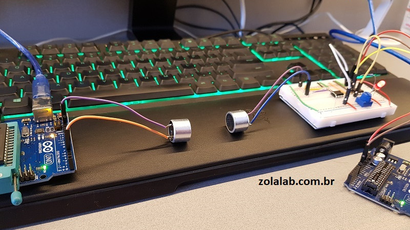
 In the video after the break, [Eduardo] demonstrates his extremely simple setup for using ultrasonic transducers for one-way data communication. Powered by a pair of Arduinos and using transducers salvaged from the extremely popular HC-SR04 module, there’s a good chance a lot of readers can recreate this one on their own bench with what they’ve got lying around. In this example he’s sending strings of text from one computer to another, but with a little imagination this can be used for all sorts of projects.
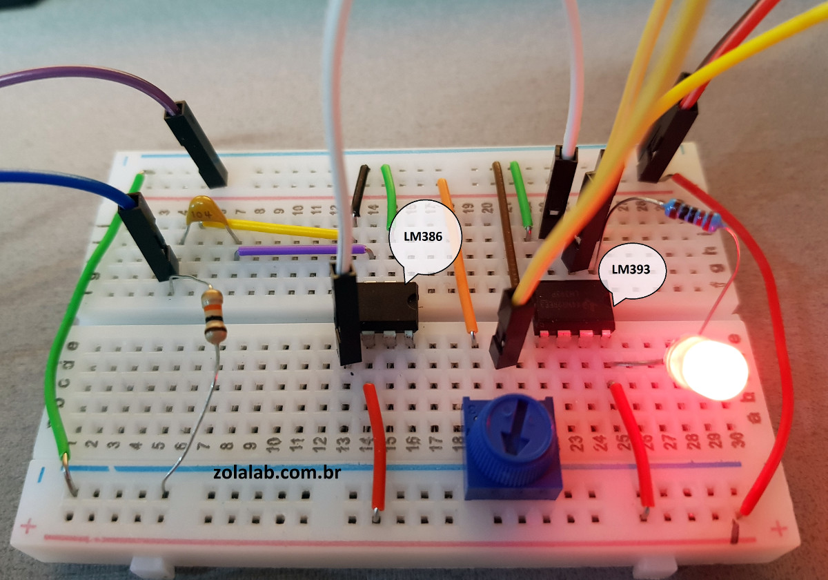
For the transmitter, the ultrasonic transducer is simply tied to one of the digital pins on the Arduino. The receiver is a bit more complex, requiring a LM386 amplifier and LM393 comparator to create a clean signal for the second Arduino to read.
But how does it work? Looking through the source code for the transmitter and receiver, we can see it’s about as basic as it gets. The transmitter Arduino breaks down a given string into individual characters, and then further converts the ASCII to eight binary bits. These bits are sent out as tones, and are picked up on the receiving end. Once the receiver has collected a decent chunk of tones, it works through them and turns the binary values back into ASCII characters which get dumped over serial. It’s slow, but it’s simple.
If you’re looking for something a bit more robust, check out this guide on using GNU Radio with ultrasonics.


Cool!. Goes for a good science fair project, as well as eliminating wires on simple unidirectional comms. Thanks for the tip
Not just unidirectional; this could be used for half-duplex comms, since it looks like it doesn’t transmit anything unless there’s something in the serial port buffer to send. You just need to switch to receive mode (and run the receiver loop) until something shows up on the Arduino’s serial input port. It should even be possible to use the same transducer for transmit and receive, just by setting the output pin to high-Z when receiving. Just one more I/O pin for the output from the LM393.
You should also be able to replace the ultrasonic transducers out for an LED & phototransistor and have this work with light. The first IR TV remotes replaced ultrasonic remotes this way, and I understand that’s why we have the 38kHz carrier that is common on IR control signals.
Just one concern: I think the receiver code doesn’t discriminate between frequencies at all – I think it relies on the transducer itself for tuning. This wouldn’t be the case for a phototransistor, so it might be susceptible to interference from other light sources such as fluorescent lamps. However, I seem to recall reading in a HaD article that the commonly used IR receiver module used in TVs somehow only detects a carrier close to 38 kHz, so if you got some of those, it might work without any other modifications beyond changing the carrier frequency to 38 kHz. Here it is: https://hackaday.com/2017/02/20/hackbusting-can-you-fake-a-tv-remote-with-a-lighter-and-some-paper/. If you really want to use regular photodiodes, it also might be within the Arduino’s capabilities to detect the signal with a certain amount of selectivity, but that’s hardly a simple modification of the code. What COULD be a simple modification, though, is to put an LC band-pass filter between the amplifier and the comparator, which is kind of what those TV IR receivers do.
you are right about that concern, this cirquit indeed doesn’t filter for frequency.
or well actually it does, but it does so based on the physical resonance of the receiver and transmitter, meaning that it won’t work with leds yet, it will however work with different Ultra Sonic tranceivers.
it is quite doable to convert this to led however. since the receiver just amplifies it and then filters out some basic static/em noise to convert it into a digital signal and tune it’s sensitivity.
both sides use a arduino uno which means that those can be used to modulate and undulate the signal, so the code would be changed to send many signals at a certain frequency rather than one signal per pulse, the receiver will then run a protocol to check for those pulses and use them to sync itself, and/or filter out things that aren’t send on that frequency.
still however, this is quite bad, it isn’t without reason tv’s have a short range and sometimes respond really slow, since there is a lot of Ir and it changes a lot as well, this causes a lot of interfearance and in general most IR protocols just keep resending the entire message untill it succeeds, often not even knowing if it succeded or not.
even at night or in the dark there is a insane amout or IR that also modulates a lot.
for a project I was doing to design a working RC boot with up to 10 different actions for around €0,15(hobyist cost, so can be a lot cheaper when you get parts for cheap like how factories get them) I first used IR, where the rc system should be really small, but it is terrible, even more so when done without modulation to save weight and cost.
I actually came to this page because I came with the idea of using ultrasonic transducers to communicate instead of radiowaves, but decided to first check the internet to see if someone has done it before and how it behaves/can be optimized.
another Idea I had and wanted to try was to use broken solar pannels and UV leds, hold a lot of energy and transmit that strong, broken solar panel parts generate a lot of voltage from it rapidly making for easy detection, and during the night there is almost no UV outside.
so in theory that would be superior in all ways over IR since IR also doesn’t work relyable during the day in sunlight, that is why many kids think they can’t controll that random IR RC helicopter or micro plane, because it just doesn’t respond anymore quite rapidly if it is sunny outside.
using broken solar cell pars also allow you to use something that normally would be waste, you could even use a solar cell shard as a UV led, but a normal uv led is much more easy to use and powerfull and also only costs around €0,02 if you buy many of them at once.(or you could use a old cathode ray if you want to be cool)
Neat article, project and socket on the Arduino also.
Nice project, Shared with our engineers. Is there any solution that we can use it?
So, what you’ve got there is an Arduino being used as a modem. Excellent. How does it encode the bits? Looks like pulse width modulation of a carrier, of sorts – it doesn’t use the width of the modulated pulse, but the width of the time between pulses, which is just inverted PWM.
My first thought was, this would be great for sending remote control signals to a model submarine. Peter Sripol built a submarine out of a toaster, which he demonstrates in fresh water using a regular RC radio. He claims it will work in salt water, too, but I believe he means the mechanical portions of it; I seriously doubt that an RC radio signal will get through more than an inch or two of seawater.
But if we were going that way, RC transmitters use modulated pulses of widths varying from 1 to 2 ms, which at 40 kHz would be between 40 and 80 cycles of carrier – plenty enough to be able to detect while rejecting out-of-band noise. So this might be another application for the same hardware and only slightly different code.
Looking at the receiver side, though, maybe I’m reading it wrong – I’m not that familiar with the Arduino library – but it doesn’t look like any detection of the 40 kHz carrier is being done. Possibly the bandwidth of the transducer itself is what rejects out of band noise. But anyway, it looks to me like it would be even easier to code it to generate servo pulses.
Check out the ELF and VLF range for submarine comms. This article is interesting also and maybe an hackable way to make a remote control even (see article on PDF page 45 or magazine page 49): http://www.americanradiohistory.com/Archive-Elementary-Electronics/1970/Elementary-Electronics-1972-05-06.pdf
The RX code just counts how many ones there are in a 10ms time span using digitalRead() (which takes 3.6us to execute, according to the Internet). Well, it’s simple, it works, data gets transmitted, client gets happy, developer gets money for new gadgets…
(I’m not the author nor am I related to him in any way)
Does this only work for having one object in the field of vision at a given time? Like, could you confuse it by placing two items such that the receiver gets multiple ping responses and things so it thinks the distance is jittering? If, so, would it be feasible to possibly account for any arbitrary number of objects in the field of view?
Great article and project. Just a random thought… what if the sender is the android device and receiver is ultrasonic transducer? will the comms still work?
Could you illustrate how the 10k pot is going to be used for tuning ?
The pot would be adjusted until you made an adequate baseline voltage against which the incoming amplified signal would be compared. This could be easily accomplished in the field, which could be useful if the distance changes, as this would attenuate the input signal more.
came here because I had this idea as well for a time and wanted to see if I could find others doing it.
wanted to use it for a RC system, since surface wave radio controll systems are no longer legal I decided to use sound waves, since they get really far underwater.
would alos be great for a RC submarine since it doesn’t require wires unlike most other ones.
I was hoping to make an RC submarine control system that uses ultrasound. I started by copying the code and schematic seen here, but then thought, “what if I just got a simple IR RX/TX setup, but swapped out the light parts with sonic parts?” Then my child was born and I haven’t touched any projects since.
Where can i get the code?