Some of the best hacks are the ones which seem perfectly obvious in hindsight; a solution to the problem that’s so elegant, you wonder how it never occurred to you before. Of course we also love the hacks that are so complex your eyes start to water, but it’s nice to have a balance. This one, sent in by [Eduardo Zola] is definitely in the former group.
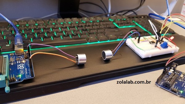
 In the video after the break, [Eduardo] demonstrates his extremely simple setup for using ultrasonic transducers for one-way data communication. Powered by a pair of Arduinos and using transducers salvaged from the extremely popular HC-SR04 module, there’s a good chance a lot of readers can recreate this one on their own bench with what they’ve got lying around. In this example he’s sending strings of text from one computer to another, but with a little imagination this can be used for all sorts of projects.
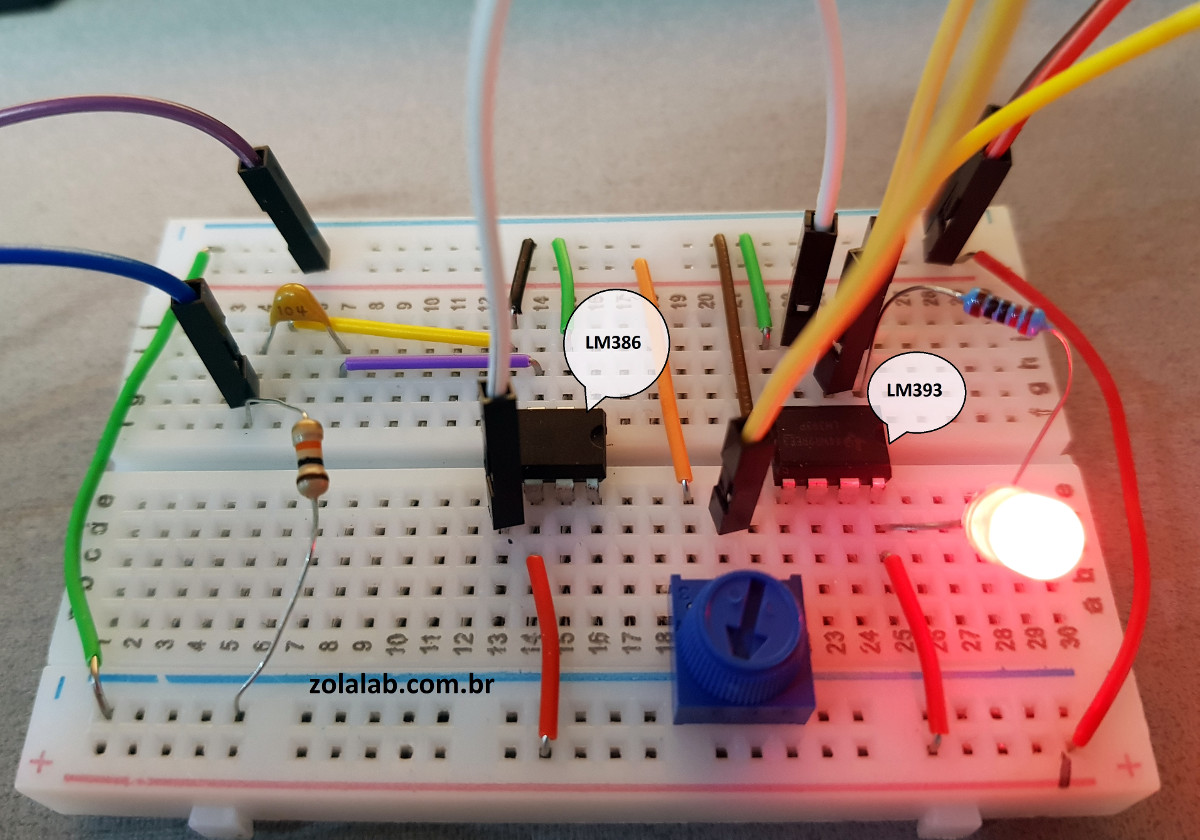
For the transmitter, the ultrasonic transducer is simply tied to one of the digital pins on the Arduino. The receiver is a bit more complex, requiring a LM386 amplifier and LM393 comparator to create a clean signal for the second Arduino to read.
But how does it work? Looking through the source code for the transmitter and receiver, we can see it’s about as basic as it gets. The transmitter Arduino breaks down a given string into individual characters, and then further converts the ASCII to eight binary bits. These bits are sent out as tones, and are picked up on the receiving end. Once the receiver has collected a decent chunk of tones, it works through them and turns the binary values back into ASCII characters which get dumped over serial. It’s slow, but it’s simple.
If you’re looking for something a bit more robust, check out this guide on using GNU Radio with ultrasonics.
Continue reading “Dead Simple Ultrasonic Data Communication”