We recently published an article where someone apparently controlled their TV by simulating a remote with merely a lighter and a sheet of paper. The paper had a barcode like cutout for a supposed “Universal Standby Signal”. The video rightfully attracted a substantial crowd, some awestruck by its simplicity, others sceptical about its claims.
Coming from some generic “Viral Life Hack” production house, the characteristic blare of background music, more suited to an underground rave than a technical video, certainly did not do it any favours. As any moderately experienced campaigner would know, modern televisions and remotes have been carefully engineered to prevent such mishaps. Many of us at Hackaday, were under the impression that it would take something slightly more sophisticated than a fluorescent-bodied lighter and a crisp sheet of A4 to deceive the system. So we tested it out. Our verdict? Unlikely, but not impossible. (And we’re pretty sure that the video is a fake either way.) But enough speculation, we’re here to do science.
Careful of the Carrier:
The most glaring inconsistency in the video’s methodology is the omission of 38-40 kHz carrier usually employed by infrared remotes.
There are two big advantages to transmitting an on-off signal using a carrier:
- Optimise the frequency of transmission to one that is more suited to the medium. This will minimise the incurred distortion and loss.
- Prevent false transmissions and signal contamination by a noisy background
The fundamental role of the carrier render it key in the command decoding process at the TV end. Receivers are designed to respond to one particular frequency. Can any of this still work if we discard the carrier?
Enter the IR Receiver:
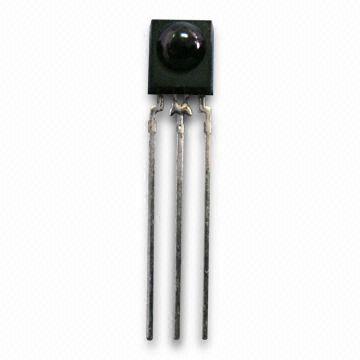
If you take apart your TV or any other appliance that uses an IR remote, you are likely to see one of these. IR receivers are usually 3 pin devices and are not to be confused with IR photo-diodes or IR transistors.
The latter completely disregard the modulation scheme and instead simply respond to the correct wavelength.
IR Receivers on the other hand, contain an IR photodiode (or transistor) and additional circuitry to restrict signals that are outside the 38-40 kHz pass band. Once an AM style modulated carrier is present, it is demodulated and presented on the output pin of the device.
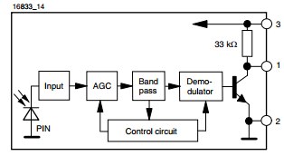
The performance of the elements, paramount to our investigation are the AGC (Automatic Gain Control) and the Band pass filter. They prevent noisy surroundings from inducing spurious responses at the output.
The AGC’s job is to optimise the gain for the surrounding ambient noise. For example, if you have a fluorescent lamp spewing out some high frequency IR thanks to the noisy electronic ballasts or even a lighter producing a low-frequency bit pattern, the AGC will reduce the overall sensitivity of the receiver. Once this signal passes through the bandpass filter it should be attenuated enough to be rejected by the demodulator. Sophisticated IR receivers even employ clever control circuitry to reject some in-band noise based on the length of the signal. It’s not looking good for the hack.
Any Hope for the Hack?
On paper this hack looks done, dusted, and busted! Even before we proceed to scrounge the datasheet in search of the Bode plot to deliver the final blow; it’s clear that the band pass filter would have to be pretty bad to leak through a signal, orders of magnitudes smaller in frequency than the nominal carrier.
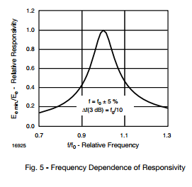
As first glance, the bandpass filter performs reasonably well. Figure 5 shows the response of the receiver to a frequency relative to the response exhibited for the nominal frequency. The 3 dB bandwidth of this IR receiver is about 4 kHz — only about half of the signal gets through at 34 kHz or 42 kHz.
Unfortunately, the graph does not extend all the way down to the low base-band frequencies we are interested in. We can extrapolate and see that the response will be severely degraded at those frequencies. However, this still doesn’t guarantee that an out-of-band signal will be attenuated enough to be successfully rejected by the subsequent stages. How much attenuation do we need exactly?
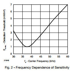
Perhaps, more instructive is Figure 2. It shows the required irradiance needed to trigger the output for a given frequency.
Almost an octave away from the nominal frequency, we only need seven times the irradiance to trigger the output. Assuming a crude linear extrapolation to the left, we need about a 10 dB gain of incident power to trigger the output directly, using a typical 1 kHz base band signal. That’s not much!
Considering that irradiance of a light source, such as a flame, follows the inverse square law. If the lighter is bought in close enough, the IR receiver might just accept the base-band signal. Has this actually resurrected some hope for the hack?!
Let’s Test This
Im not going to lie. I was hoping this investigation demand some thorough “on the bench” tests, rather than just lending itself solely to some book-work! The insight offered by the graphs has certainly given me an excuse to fire up the oscilloscope!
I have decided to proceed in a civilised manner, one that does not involve hacking some A4 and creating a potential fire hazard. Instead im going to make it easier for his hack to succeed, by idealising all conditions. What we need a series of tests to demonstrate whether an IR receiver would faithfully reproduce its input, regardless of it being presented in its low frequency base-band form or its high frequency carrier embedded form.
Test One
For this test I wanted to see how a simple IR transistor would behave with a flame present. I probed the collector of a IR transistor and found that it was totally sensitive to the lighter. As soon as the lighter is ignited, the transistor saturates, recovers and continues to respond to the flame. Now considering the amplification stages present in IR receivers this could potentially cause havoc.
Clearly, the lighter is a very strong source of IR, which is ideal when trying to fool the IR receiver.
Test Two
Lets move on to the actual IR receivers. I had two types in my parts bin. I powered them up, probed the output pin, and fired up the lighter. To my surprise all of them were fooled as far as to produce some bit pattern at the output. I could even get a response from across the room!
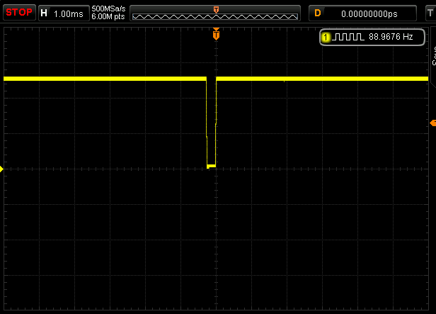
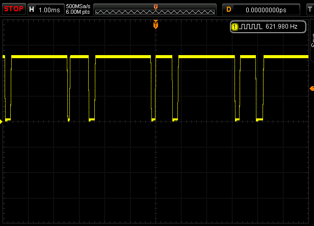
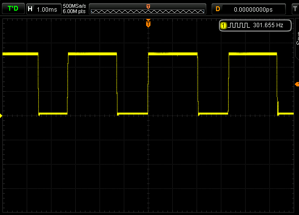
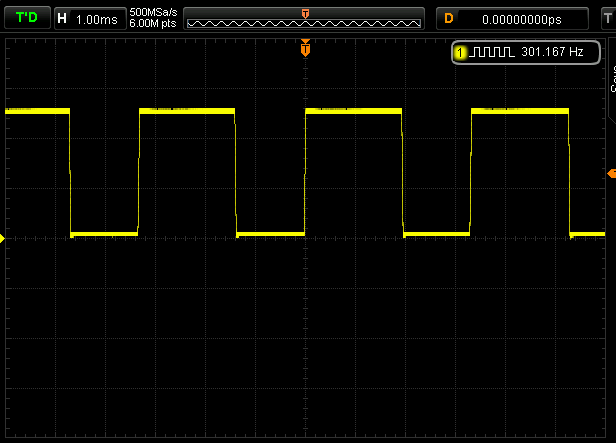
However, the sensitivity and response depended on the receiver used. The ones with the metal shielding performed a lot worse than the bare black bodied one. In fact, look at the two scope shots below. Can you differentiate between the bit pattern associated with the remote and the lighter?
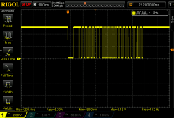
Interestingly, the IR receivers offered no response to the lighter, after the initial ignition. This is mainly down to the AGC finally compensating for the blinding IR source and the over all high attenuation low frequency signals experience through the IR receiver.
In any case, this makes the investigation interesting. It is clearly possible to induce some sort of bit pattern using a lighter! But can this be used to produce a deliberate pattern or are we always just confined to error prone gibberish? Lets build a test rig to get to the bottom of this!
Test Three
 The results from test two were a bit of a revelation. We now need to test whether a reliable bit stream could be produced with a lighter or any other deliberate low frequency IR perturbation. Lets test the ideal case: a high-power IR LED outputting the base-band (no carrier) bit stream in close proximity to the IR receiver. Do we get the exact replica at the receivers output?
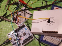
To keep the test data as realistic as possible, I wrote a quick program on a STM32 to read a bit-stream from my remote and output that like for like to an IR LED, minus the carrier. I then taped the IR receiver and IR led together, and placed the whole fixture in a cardboard veil. Comparing the output of the IR receiver to this emitted bit stream will decide the fate of this hack.
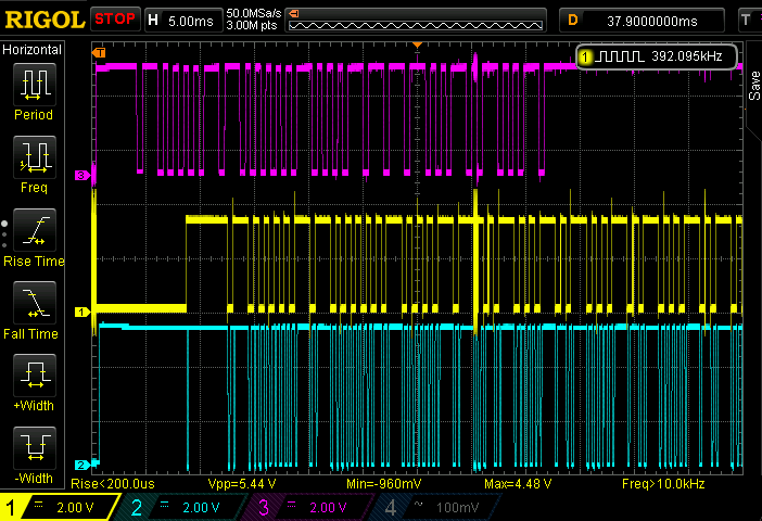
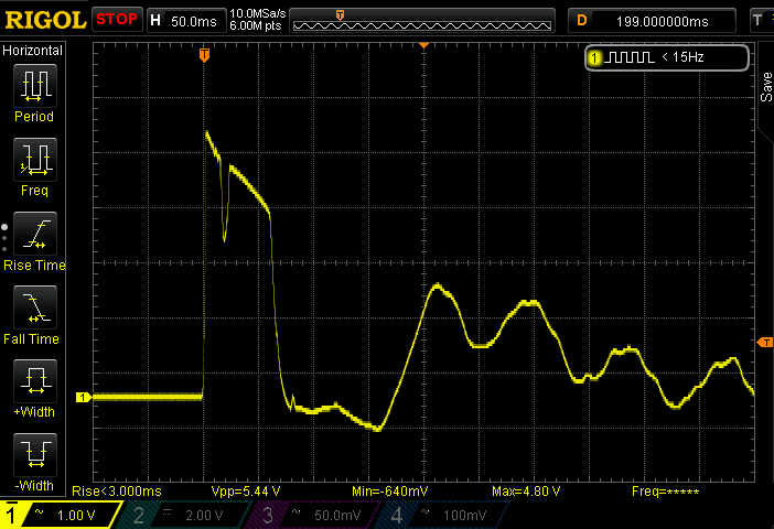
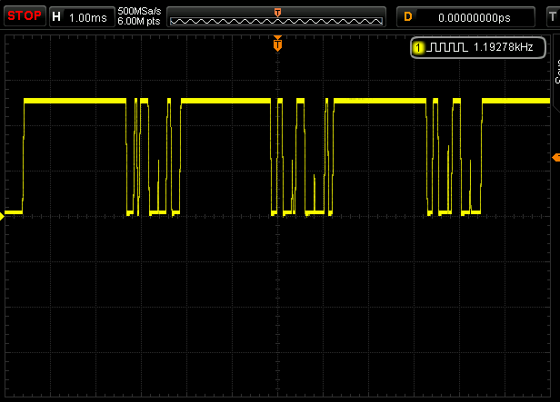
The trace on the top is the demodulated signal produced by my TV remote. The trace in the middle is the output of the IR LED being driven by the MCU. Finally, the trace at the bottom is the output of the IR receiver. At first glace it seems to have worked!
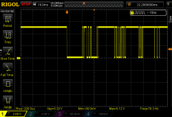
Here is a zoomed in section of the second and third trace. They must be identical for the hack to work:
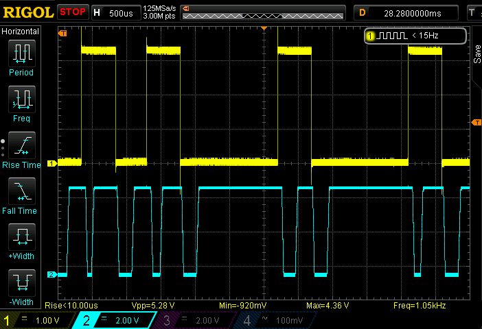
Uh ohh. Clearly, they are not the same. Repeating this experiment multiple times, even with different kinds of IR receivers, I have noticed that the error rate is extremely high and the bit patterns produced are absolutely not repeatable without the carrier. In this case we see two output toggles for every one input toggle. This, I suspect, is an artefact due to the demodulator not being happy with the out-of-band frequencies.
Even though there is a strong correlation between the two signals, it is certainly not enough to fool a TV. I’ve tried pointing this IR LED to the three TV sets I have, none of them even budged.
Can An Obstruction Produce Any Bit Pattern?
The last thing to test is producing some kind of bit pattern using an obstruction. This is a bit redundant as the last test has shown, low frequency signals produce erroneous data at the receivers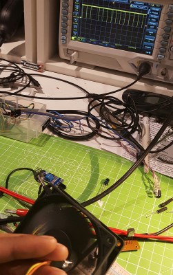 output anyways. Manipulating this to get a valid code is difficult or impossible.
IR receivers are incredibly sensitive devices. For example, trying to prevent your TV from registering a remote press by covering the LED is not easy. Unless you try very hard, it cant be obstructed. Thus it is very likely that without turning the strong source of IR off, a simple cutout based obstruction will simply look like a flat, always-on signal to the receiver.
To test this, I tried various card based obstructions in front of a constant IR LED and lighter. Moving the card back and forth several times landed me nothing.
To turn things up a notch, I decided to use a PC fan as the source of obstruction. Spinning at about >2000 RPM with seven blades, gives a frequency of 250-300 Hz. This worked pretty well without a carrier, but produced the wrong bit pattern on the scope.
Next, to simulate a carrier I flashed the IR LED using the function generator, instead of turning it on constantly. I set the flash frequency to 38 kHz and voilà, the perfectly demodulated 300Hz signal being produced by the fan, appeared on the scope! However, if I now deviate away from the carrier by a an octave or so, I see an erroneous pattern again.
The photos below show how the worst performing IR receiver I had, demodulated the 300 Hz input signal caused by the fans, for a given carrier. Only the 10 kHz and 38 kHz carriers were successfully demodulated to reveal the underlining 300 Hz signal.
The Verdict
Is the video fake? We’d put our money on it. But is it possible to produce bit patterns on the output of an IR receiver using an obstruction and an IR source like a lighter? Yes, and we’ve demonstrated it. Are the bit patterns produced in this fashion repeatable and error free? Nope, and this is the crux of our skepticism. Is there even a little chance this could work, considering the multitude of IR receiver types in the market? A slim chance, but definitely a chance. If the IR receiver has dubious bandpass filter characteristics and is happy to work at a much lower carrier, it might just be plausible. But it’s not easy, and it’s not a life hack, whatever that means.


LOL. The science sparked from user comments ?
I sometimes get really good and unique ideas by taking naive questions and applying some serious out-of-the-box thinking
Great write-up. My only question is about harmonics. Technically, if you created a bit pattern of Carrier x Signal, a mixer [1] should produce a signal of f1 + f1 (and f1 – f2) right? And since these are square wave signals, the Fourier would contain a component at ever N*Carrier right? [2] So Could you not print out a bit pattern of some integer divisor of the carrier (minus the bit rate of RC-5 protocol of 562 bps) and multiply/mix with your signal and get some (small) signal component of that at 38kHz? Or maybe not, I don’t know it’s been a long time since signals class :) Second option… if the “bits” on the paper are 1 mm wide, maybe you could just move the paper fast enough? I think it would be 38 m/s or about 85 mph to get 38kHz signal? Fast, but slower than some baseballs are thrown, and certainly faster than what was shown in the video.
[1] https://en.wikipedia.org/wiki/Frequency_mixer
[2] https://en.wikipedia.org/wiki/Square_wave#Fourier_analysis
Thanks!
Interesting point about, generating the carrier by moving the paper fast enough. Interestingly, if you look at the last test I did, some IR receivers are happy with even a 10 kHz carrier, meaning you only need to move it fast enough to attain the lowest acceptable carrier.
Yeah, I had a CFL light at some point and for about 30 seconds – 1 minute after turning it on anything that used an IR remote did not work. I used some IR receivers and found that while the light was starting up they were all producing random bits at output.
Additional question not answered – Is a typical sheet of paper opaque enough to block IR?
It may not be, but I think it causes enough variance between the HIGHs and LOWs that can trigger the receiver. what I’m skeptical about is the flame, as this is not similar to an IRLED. The flame can sway from side to side ignoring whether a thin piece of paper is blocking it.
A while back I built a circuit with an opto interrupter, and cut a wooden disc about the thickness of a matchstick to block the IR LED. I was getting almost no signal until I painted the wood black, at which point it worked extremely well. I was pretty shocked at how wood that blocks light fine seems to suck at blocking IR.
Unless the IR was bouncing off the unpainted wood and illuminating the wall behind you?…
not only busted but a clever way to exploit the pay per click partnering system.
the music in the video is probably some copyrighted song tweaked to avoid detection by copyright checks.
if you are thinking of using youtube to pirate you are better off with the piratebay or other torrent sites.
if you are trying to profit from the piracy then exploit the private flag and post the password to the video (yes you are then potentially letting others into your google account even to your gmail account.
Love it, is there anyone who actually tested this?
Yes, Adil tested this and wrote this article based on his results.
TL; DR: “Even though there is a strong correlation between the two signals, it is certainly not enough to fool a TV. I’ve tried pointing this IR LED to the three TV sets I have, none of them even budged.”
Haha nice one HAD.
Read the title – remembered the previous article – didn’t bother with the rest of the post – assumed level 9000 backtracking because it’s not uncommon for HaD to post complete unverified crap. What’s worse than unverified materiel – a poor attempt at a justification. Classic HAD.
So you didn’t read the article, but still took the time to post a comment to the article about how you didn’t read the article?
I didn’t read the comment. Also, I’m looking out the window as I’m typing so as to not read my own reply.
LOL!
TL;DR: L
He must be from Slashdot.
I am surprised that this article does not begin with an attempt to reproduce the actual claim, i.e. use a sheet of paper and a lighter, have it work (or fail) and then go from there to explain why or why not. This is more of an anti-feasibility study than a real refutation. It is a nice article all in all and I learned some things about the IR detectors on some boards I have, but ….
I agree. Bar-code on paper with a lighter or you didn’t disprove it. What if the paper some how modulates the signal correctly? Plus you’re a hacker.. Fire hazards scare you? HAH!
Being a Hacker is exactly what prevented me going down a path testing TV control using some so called “Universal Standby Signal”. There is obviously no such thing. LOL.
Well you’re obviously more experienced and smarter than I at this subject. So i will take your word for it. But me personally had I heard about using fire to create a signal of some sort. I would have had to test it with the fire. But to each their own. Either way it was an awesome post. I just like to poke fun :) Thank you for the great write up and test.
Thankyou ;)
The only way for it to work would be if the gas leaking out through the open valve of the lighter “whistled” in desirable ultrasonic range, thus modulating the flame too fast for an eye or an ordinary camera to detect it. We would need a very high frame rate camera to conclusively catch that, and I would be very surprised if such an hypothetical phenomenon would had the right pitch.
There wasn’t enough info in the video to recreate anything accurately, though. You couldn’t be sure if your reproduction fails b/c there’s no effect, or if it fails b/c you failed to reproduce the right conditions. The original “claim” is so vague that there’s really not a claim — just a clickbait “lifehack” video. Sigh.
So Adil attacked it from the ground up. (I did too, completely independently, just for fun.) It’s surprising how much leaks through the detector, especially while the AGC amplifier is ramping up or down. But getting a TV remote signal out of that noise is going to be very hard, to the point of nearly impossible. And I think Adil demonstrated that pretty well.
If anyone can send us a PDF of the right paper cutout pattern and exactly the right TV to do the test on, we’d be glad to oblige.
I knew it probably wouldn’t work because of no 38Khz modulation but tried to reproduce the claim anyway on five different tvs.
Even if the band pass circuit is leaky you’re not going to get the rest of the timing right unless you’re commander Data.
Wait. You’re really telling me somebody actually tried this? And I don’t mean simply as proof of no – concept. I mean somebody actually tried this thinking it would work?
Dang man!
HAD published it.
!!!
FAKE NEWS! OMG there IS such a thing!
“I mean somebody actually tried this thinking it would work?”
I don’t think Adil thought this would work…
In science reproduction of questionable results is often performed, as results ought to be reproducible…
Biomeds should know this?
Needed no reproduction, just a simple look at the physics as presented in the photographs headlining the article. Flame 3/8″ wide or more, Slits in paper too close together as well as each too wide. The estimation arrived at was the detector 10 foot away would receive illumination through multiple slits at a time rather than one at a time such that it would be unlikely to ever see a “not illuminated” condition. To correct for this it simply needs a stationary collimator slit in between the flame and moving paper with encoded slits to narrow the beam to allow a fully dark condition to be attained between illuminated encode pulses, then concluded the article a learning exercise still in progress with success possible and even probable but reported as success too early. There were waveforms presented, showing about the level of function to be expected would be had without the needed collimator, hence on the right track, but just not done working it out, A premature claim of success at worst when still just one more puzzle to be overcome. .
Then I see it called a fake, More correctly it should be called something like…. the normal learning process.
But now he’s been called a fake. Someone has to go back and apologize to him/her. Someone should forward my above text to help this inventive person finish it with success…. and HAD apologize. .
He’s gonna havta have ONE HUGE LONG strip of paper with tons of little slits to make 38kHz! Or buy a lighter with 38kHz flame modulation. ;D.
Nice job, very interesting article, thanks for sharing :)
Note: “viola” means “raped” in french, which is far away different than “voilà” :)
Oops, fixed. Thanks!
not quite. violé means raped.
violé means raped as in “I was raped”
viola means raped as in “he raped me”
Both mean raped, and both tend to make French readers uncomfortable.
Nice job! Very clear and well thought out analysis. Perhaps you could put together some training material for HaD editors on spotting bogus clams ;-)
Thankyou!
Bogus clams can usually be spotted by the odor. ;-)
Spotted clams are usually bogus.
Nice Job.
You did a good job.
Thankyou!
I agree, great stuff Adil!
Test 3 suggests that one pulse gets through the receiver for each edge from the emitter. Which makes sense, because that square wave edge is 38kHz as much as it is any other frequency, right?
Assuming whatever is reading the baseband further downstream in the TV is only looking at rising or falling edges but not both, it might be possible to trick the TV by creating an IR signal that only transitions hi/lo or lo/hi at the start of each expected pulse in the baseband.
There was a time when TV remotes were super simple and this would have worked. Anyone remember the original ‘clicker’ remote? Right after that remotes went IR nut super simple, mostly just the presence of light or simply flashes. One could sometimes activate the TV with a flashlight or even mirror from sunlight coming in the window.
So yes, it can and does work, with a very limited target set of TV’s.
Its like that unlock your car with a blast of air, it works on one crappy model of car (whose locks happened to be actuated by air) so people assume it works with all models of cars. Same here what works with one model can’t be assumed to work with all models.
The original clicker clicked because it was a small hammer striking an ultrasonic-range sound bar, like a xylophone
Yes and the early tv’s responded to that sound. After that they replaced the sound with IR but it was still just simple, not modulated or anything. I remember just having power and channel and still had a manual knob and when you hit the channel button you would hear the clunk from the solenoid that rotated the channel knob one channel. Those were the ones that could be fooled by this method.
Anything made past the early 1980s is going to want a carrier and be picky about the timing.
My point is that this isn’t completely busted, there were some models of TV’s that it was possible. early 80’s sounds about right from my childhood memories.
One of the TVs I tested was a 1980s Sony trinitron.
Ooh, now I really want to build one of these.
“…trying to prevent your TV from registering a remote press by covering the LED is not easy. Unless you try very hard, it cant be obstructed”
Well… I guess I’m superman then, I can block IR signals with my finger
But seriously now, depending on the receiver, the signal does not need to be blocked perfectly. As long as the light varies in intensity it COULD be enough to be detected. After all, the amplifier is not DC coupled otherwise it would be having too much problems when exposed to sunlight (standing close to a window for instance). But anyway, the video is fake for one simple reason… there is no universal standby signal. Anyone who ever seen a universal remote control has most likely also seen the manual that came with it. It is a A1 sized piece of paper with very tiny printing that shows hundreds of different TV models and their codes you must enter in order to send the correct IR-codes. If their was something like a universal OFF code, then why did they not make a universal vol+, vol-, ch+ and ch- etc…
In the 90’s I had a very expensive (but useless) universal remote control, it had a very nice feature, you could call a telephone number, hold the universal remote with it’s microphone to the earpiece of the phone and then “download” new remote control codes into the device. Seriously no kidding. But in real life it was just a very unpractical piece of sh…
And I decided it was better to keep using the original remotes, because only then I could use all the functions of the device I was trying to control. For some reason universal remotes are always crippled because they just miss those very important button that don’t seem to exist on other devices.
The real question is: what is the code on the paper i.o.w. what does it really stand for?
Anyone?
I expected the barcode pattern cut into the paper would be random, but it turns out that it actually encodes a real IR remote signal, specifically a CD player digit 5, encoded with 12-bit Sony format. Obviously this won’t work to turn off a TV, but I’m surprised that the paper template is based on a real code. (The various constraints make it very unlikely that you would end up with a valid code by chance.) A wide slot indicates a 1; reading the slots right-to-left you get 10001,0000101,start, ie. 17,5, where 17 indicates a CD player signal and 5 indicates the digit 5 was pressed.
Note that the video is fundamentally flawed because there is no standard signal to turn off a TV. The TV-B-Gone is a gadget that will turn off almost any TV; it sends 100 different signals to do this. (I did the Arduino port of TV-B-Gone.) So even if you did cut the correct code into paper, modulated the signal correctly, and moved the paper at the exact right speed, you’d only be able to control one brand of TV in the best case.
Precisely! Thankyou for your comment and insight Ken! Love your work. Trust you to decode what the code is by merely looking at a high res photo of it ;)
Well, turns out you can use a lighter to turn off any (and I mean any) TV. It is simple:
1) Ignite lighter
2) Use flame to light fuse on stick of dynamite
3) Place dynamite under TV
However, the process isn’t reversible.
it has been in me experience in years of messing with learning remotes that all devices receiving IR has a level of “good enough” (error correction) Im sure with some effort person could have found an on off signal that would have done something.
Early I was bit confused all about the burning of a paper
Thanks Adil you solve this puzzle. Wonderful man
I had soviet TV (from about 1990) that sometimes glitched and changed channels or settings by itself, with LED signaling “received command from remote” flashed. But it might be caused by other reasons, not light patterns.
Back in the day my friends dad had one of the first remote control TV’s I had ever seen. It was sound based and the remote had only four buttons. If you looked into the front of the remote you could see four rods of varying length. The press of any button produced a loud click (and is why old folks refer to tv remotes as “the clicker”) and the tv responded accordingly. The four buttons were channel up, on/off, volume up and volume down. The channel button only went one direction so if you wanted to go from channel 25 back to channel 7, you kept clicking till you reached the last channel and the tv would then wrap around back to channel 2 (at the time I believe channels only went to 33 or there abouts). The old ray gun toys that make a lot of sparks could also change the channel.
FML I’m old.
I was able to change the channel on an old set by jingling my keys.
“…trying to prevent your TV from registering a remote press by covering the LED is not easy.”
Tell that to my old Vizio. Some stupid little tchotcke set on the stand in front of it, off to the far left, managed to completely block the remote signal from getting to the IR receiver. It wasn’t very close to the front of the TV, had to be more than 1/4″ gap between it and the front of the TV frame.
Remember when TV’s had text on them pointing out where the remote receiver is, or made it plainly obvious where it is? (And control buttons *on the front* instead of on the edge, or around the corner on the back side.) Style over intuitive usability.
Who has engineers who don’t put the IR receiver in the center where people will naturally point the remote? Vizio, that’s who. They should share a drink with the people who designed the original iPhone 4 antenna.
I recently bought a TV that doesn’t have a single button on it. And I use it for my secondary monitor, so it’s kind of annoying. For now, the remote is safe on my desk, but when I lose it (or the children help me lose it), I’m going to be crazy/angry enough to try turning it on/off with strips of paper and a lighter.
I also used to have one of the “tuned rods” TVs, IIRC it was a Telefunken.
Interestingly despite the blue and green going out over time the red phosphor still worked when it finally got scrapped.
My college roommate and I back in the 70’s took the ultrasonic receiver circuit out of an old Zenith (I think) “works-in-a-drawer” color TV and used it to build an automatic door opener for our dorm room. The receiver detected the ping from the remote and turned on a large solenoid stolen from an old washing machine, which was connected to the door knob by an extremely high-tech spring, coat-hanger and duct tape deal that turned the knob and opened the door. Never mind the fact that the room was only 10 x 15 feet and a good yawn could make your hand reach the doorknob from anywhere in the room…