Have you ever torn open an Ethernet jack? We’d bet the vast majority of readers — even the ones elbow-deep into the hardware world — will answer no. So we applaud the effort in this one, but the conclusion landed way off the mark.
In the last few days, a Tweet showing a Raspberry Pi with its Ethernet socket broken open suggested the little PCB inside it is a hidden bug. With more going on inside than one might expect, the conclusion of the person doing the teardown was that the Raspberry Pi foundation are spying upon us through our Ethernet traffic. That’s just not the case. But we’re still excited about what was found.
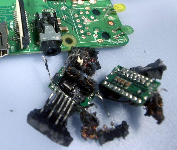 The truth is rather more obvious to anyone who has spent a lot of time working with Ethernet interfaces. To confirm our suspicions we had a chat with Roger Thornton, the Principal Hardware Engineer at Raspberry Pi Trading, and the man with his finger on the pulse of what goes into a Pi. He was very happy to confirm in a fascinating conversation about sourcing Ethernet jacks with integrated magnetics, that of course the Pi contains no surveillance hardware. Instead what our Tweeter had found are the magnetics, the isolation transformer, and some filter components included because the latest Raspberry Pi version (Raspberry Pi 3 Model B+) has support for a future Power Over Ethernet (PoE) add-on.
It is these filter parts on their little PCB that seem to have captured attention as possible nefarious parts, but in debunking the whole idea it’s worth taking a look at the magnetics themselves because they are an interesting and above all inexpensive part that has some uses outside the world of Ethernet.
What Goes Into an Ethernet Jack Anyway?
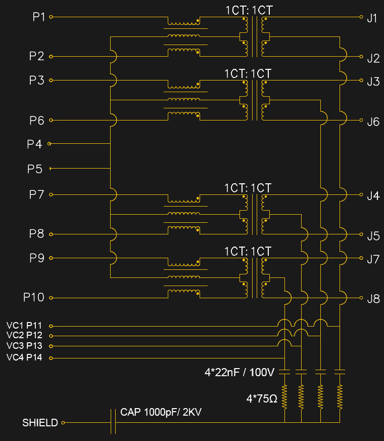
[Roger] was kind enough to give us the schematic of the jack used in the Pi, though it is typical of such jacks and bears very little difference from that you’d find in any number of other nearly identical components. At its centre are a row of four transformers, which serve to isolate the Pi from whatever stray voltages may be present upon the Ethernet cabling. To the left of each transformer is a trifilar choke to cancel out any common-mode noise that may have arrived via the cable. At the bottom is a set of RC filters on the PoE power lines which were probably the components that ignited the controversy.
The transformers have a bandwidth from about 250 kHz to 100 MHz which allows them to ignore the low frequency 48 VAC of the PoE, and pass through the Ethernet signals. In the case of the Pi 3 B+, the PoE lines are taken to a header on the board, which will mate with an upcoming PoE HAT that will contain a switching PSU with its own 1.5 kV isolation transformer to preserve the barrier between the Pi and the line.
An interesting aside to the conversation came in that some companies wind their own transformers while others buy ready-made ones. An easy way to spot the in-house ones it seems is that they will usually be concealed under some black sealant as is the case with the one in the Tweet, while the bought-in ones will be standalone potted components.
Hacking Ethernet Components
![]()
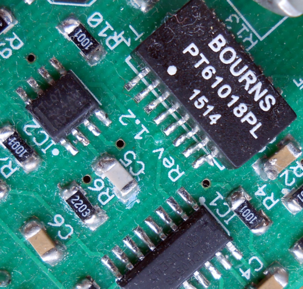
Ethernet transformers are available in a range of packages, from those built-in to sockets like the one on the Pi through various surface-mount packages and even through-hole versions on older devices. They come in three main categories which as you might expect correspond to the different Ethernet standards. 10 Mbit components usually have two transformers in one package and a bandwidth from about 100 kHz to 10 MHz, 100 Mbit ones have two with a 300 kHz to 100 MHz bandwidth, and 1000 Mbit ones like the Pi component described above have four 300 kHz to 100 MHz transformers. The transformers themselves are wound onto tiny ferrite rings, and are almost always 1:1 centre-tapped with a 600 Ω impedance and a common-mode choke on one side as described above.
Within those limitations they can be used for a variety of small-signal RF tasks that can work within those impedance ranges. By using only one half of the winding that doesn’t have the common-mode choke they can be configured as a 1:2 transformer with a 300 Ω input and a 600 Ω output, for example. In bandwidth terms they also have useful performance some way beyond their advertised specification, for example here in Europe they will pass through long wave broadcast stations at around 150 kHz to 200 kHz, and at the other end of their range they will pass through FM broadcast stations at 108 MHz. Within that range you have the entirety of HF and the lower end of VHF, allowing for example the use within every amateur band from the MF bands to 6 m and 4 m if your country has an allocation. Where this is being written they are the go-to transformer in homebrew receivers and small-signal stages for example, where they are infinitely preferable to winding a toroid.
Sometimes it is easy to believe that an application-specific component such as an Ethernet transformer could have no other uses, but it’s worth reading data sheets and asking the question as to whether any useful components lurk unnoticed in your junk bin. Take a second look, you’d be surprised what you might find!


> ignore the low frequency 48 VAC of the PoE
PoE is DC, matching all of the 48VDC telecom equipment floating around.
Wouldn’t an isolation transformer require AC though? Does PoE come pulsed over the twisted pairs along with the data somehow?
Forgive me, I’m not up to speed on the grittier details about power over ethernet.
i don’t get it either. Is J1-J8 the input?
J1-8 are the connections to the cable. P1-8 connect to the Ethernet chip. Each of the four power input lines (VC1-4) are connected to a pair of diodes just in front of the local power supply, one diode pointing from the VC pin to the VCC-RAW rail and one pointing at the VC in from ground. Another way to picture it is the four VC lines connect to the four AC inputs of a pair of bridge rectifiers with the two + outputs and the two – outputs of the bridges connected together. This accommodates multiple power over ethernet schemes and makes things independent of polarity too.
The bit that converts 48VDC to whatever’s used inside the PoE-powered device isn’t shown. The magnetics inside the ethernet jack are just enough to let something extract that higher voltage.
It’s DC phantom power. Originally, two pairs were used for power, one pair is raised to a higher voltage than another pair via the center taps on the power source side. The power sink side extracts the power via the center taps. In more recent versions, all four pairs are used to send power, with two positive and two negative. If memory serves, these are DC isolated from ground at both ends.
The pins for the PoE come off the center taps of the transformer and receive the common-mode DC voltage on each pair. The PoE module (not pictured) is a switch-mode power supply of some kind which chops up the DC into high-frequency AC before sending it through the transformer in that module.
I think there is more than one method to perform PoE.
I am making a PoE for a surveillance camera (one of those projects that looks like a kit in a bag waiting to be soldering together) and I haven’t worked on in a few months and even forget the details and had to double check.
Mine is 12V with a 5.5mm x 2.5mm barrel plug female on one end RJ45 connector box and a male on the other end RJ45 connector box that will use two of the not connected RJ45 wires to send the power. The power won’t be hidden as a pulse modulated signal in one of the data wires as I guess this is what is going on for a pass through system like a router or some device like the Pi, where mine is PoE injection I guess you call the method. I’d think there would just be the not connected wires used for the DC power whether analog or pulse modulated though I haven’t read into systems that might use more of the wires for more data transfer maybe to achieve higher data transfer rates or other controls objectives.
Just keep in mind the dc loss over the length of cable and at high currents it can cause cable heating, this is why the 48v at lower current is used. If it’s a short distance and low current then power injection is probably the cheapest route to go. I on the other hand have to keep to standards within a hospital so no go for me :/
Good call, makes sense.
Does look like some are more complex AC 48-57V on the send side and then stepped down to the appropriate voltage on the receive side and converted to DC with a full bridge rectifier. I’m guess this is for longer runs of cable.
There are. But there’s a set of standards, and then there’s a handful of proprietary methods. In the 802.3af PoE standard, it defines two methods: One uses the same pairs as the 10/100Mbps data pairs, the other puts power on the unused pairs. Keep in mind that in gigabit ethernet, there are no unused pairs, so your method won’t work for that.
The PoE standards don’t modulate the power onto the signal. It’s phantom power: A DC signal impressed onto an AC signal. In the case of PoE standards, it’s fed onto pairs via the transformer center tap, and extracted from center taps at the other end.
POE is a technical term with a strict definition. It has a protocol where the power supply will provide a little bit of power allowing the client to negotiate how much power at what voltage it wants and then that voltage is provided.
There are a few tricks that will also transfer power across ethernet cables, but those should not be called POE.
Thanks for clarifying. I still need to read into PoE in detail. I just did a quick wiki read and see I wasn’t realizing the standards since I was only looking at schematics from google images for the most part and a youtube video or two regarding adhoc designs. https://en.wikipedia.org/wiki/Power_over_Ethernet
not really. if you’d said 802.3 POE you might have a point. But POE implementation far predates the IEEE standard.
IEEE has formally defined standards that are used by the industry:
802.3AF defines the standard for PoE (up to 15.4W of power per device)
802.3AT defines PoE+ (up to 30W power delivery per device)
There are other standards going up to and even passed 50w per PoE device.
These standards include the mechanisms that allow a device to indicate how much power it will draw as well as how much power the PoE port in the switch can provide.
So this is the weird bit. The input is a DC waveform. Instead of being ground±2v, it’s 48VDC±2v.
But this works, because it’s not the absolute value of the magnetic field that excites the follower, it’s the change. Otherwise transformers would not work in the presence of any competing magnetic field!
So as I understand it (caveat emptor!), while ethernet might regularly deliver pulses of -2 and +2V, sending 46 & 50V excites the same changes in the follower – it’s still creating ~4V worth of change in the magnetic field. Then the (input) 46-50V continues out the other end to the PSU (or in the p3b, a set of headers that you can plug a psu onto), and the excitement generated in the follower comes out the signal pins.
It’s similar to the way the ripple in a poorly rectified DC supply, manifests as a hum in audio equipment. The ripple creates a waveform you can hear – it’s just a waveform referenced to the supply voltage instead of referenced to ground.
PoE is not AC, it is definitely DC, and it can go as high as 57V.
It’s cool that you debunked these concerns, but I’m surprised at the dismissive attitude toward the person who did the tear-down.
After all, their concerns are not without precedent: https://www.schneier.com/blog/archives/2014/03/firewalk_nsa_ex.html .
Pair this with the increasingly closed nature of the Raspberry Pi and it’s not unreasonably for any hacker worthy of the label to be suspicious.
I don’t think that’s what we have here, but it certainly is rational and good to check these things out. I myself always assumed that the inside of an ethernet jack was just a bunch of conductor wipes like any other. Good to know.
Now what I’d love to know is if anybody has found a way to remotely induce a signal inside those tiny toroid transformers in the isolation section of an ethernet jack to inject packets. It would probably require a magnetic field with a very short range, but it would be a cool exploit. Perhaps no more practically effective than just plugging in your own ethernet cable.
Interesting idea. That said, it MIGHT be an easier back to sniff traffic coming off of the small RF field coming off of those transformers WITHOUT being noticed by a Time Domain Reflections if attempting to physically tap into the Ethernet cable (or the Cisco equipment with built-in TDR functionality on each port).
(hack)
(Reflectometer)
Pesky spellcheck!
If you go out looking for a boogie man, you might find one. This “researcher” made some serious accusations without doing even the most precursory investigation.
If you don’t understand how something works, you probably shouldn’t crack it open and claim espionage as your first explanation.
I don’t know. Not to get all “empirical” on you, but this seems to have been more effective at getting to the bottom of things than simply asking for help.
How many of you would have jumped in to provide this analysis if not for the inflammatory claim?
https://xkcd.com/386/
Classic
If I had seen a request for information about what is in an ethernet jack, I would have responded.
I don’t doubt that (you are an exceptionally nice person Bob :) ), but what I’m saying is that without the controversy, would anyone here have heard the question in the first place?
It’s anti-vaxxer logic.
Or a flat-earther :-D
Jumping to conclusions deserves to be dismissed if not outright called out for being dangerous when your conclusion is a public accusation about something. Bonus points when that something is something he knows clearly nothing about.
Now that this is out of the way we really should focus on more important things, like how governments have been planting cats in our houses with implants where when they flip a switch will cause natures perfect killing machine to revolt and dismember their owner.
Are you going to be dismissive of that claim of mine? Even if I said it would hurt my feelings if you did so? You better be, it is stupid and deserves to be called out as such.
You said: “planting cats in our houses with implants where when they flip a switch will cause natures perfect killing machine to revolt and dismember their owner.”
Nope, all cats are like that. No chip necessary.
They tried it once, cost a bundle and on its first mission it got run over by a car
https://en.wikipedia.org/wiki/Acoustic_Kitty
Wow….speechless….some how this makes the current administration a lot less comedic
I love it when someone tries to make up something so absurd that it’s patently obvious that the CIA wouldn’t have tried it. And then they did.
Different department, same degree of jaw-dropping: https://hackaday.com/2018/04/11/hacking-when-it-counts-pigeon-guided-missiles/
If the RPi foundation wanted to spy on us, they don’t need to do it in hardware. 95% of us use their SD card images, including a binary blob.
“but I’m surprised at the dismissive attitude toward the person who did the tear-down.”
Because the proper response should have been “hey, what’s this thing inside the Ethernet jack?”
“After all, their concerns are not without precedent: ”
The object he found inside the jack is a handful of tiny components. As much as it would be cool to believe tech has advanced so much that we can put a full-fledged system on something like that… it hasn’t.
Did you read the article I linked to? It’s old school brother
In reply to Jason Gullickson’s comment about firewalk being hidden in ‘just a few passive components’ – it’s definitely not. It’s a marvel of miniaturization, but the image shown in your linked article is for a double-tall Ethernet jack and it still looks a bit thicker than my Pi’s … yep, my Pi’s is ~.85″ “deep” (in the direction the connector is inserted) and theirs is 1.13″ “deep”, plus double-stacked. Also, the Pi’s is shielded all the way round, rather than just at the front 2/3, which means that they’re in for a heck of a time getting a useful amount of RF in or out.
As stated earlier by many others, the complaint here isn’t that the person was looking to verify that things were as the Pi Foundation claims – we’re all happy to have another set of eyes taking a look and finding the fun in teardowns and verification. The complaint is that this person didn’t do the bare minimum of research to verify that their claim is plausible. For having torn the port apart like that, they would have been able to inspect every millimeter of wire and inductor core, even busted the inductor core in half, to look for any circuitry advanced enough to make an implant like this work. That, or they could look at it, take a couple minutes to learn about RF propagation through free space around shielding, and consider whether this even leaks enough RF to make a TEMPEST-style attack practical, and at what ranges.
Today’s XKCD was surprisingly relevant: https://xkcd.com/2001/
Fantastic
Also this researcher has a history of making bold claims and then having them disproved: https://en.wikipedia.org/wiki/BadBIOS
Lovely
isolation.
I don’t know if this is what they were trying to express, but there is a Maintain Power Signature (MPS) that uses 100Hz AC, called ACMPS. The idea is, when that particular frequency is attenuated by the device, the switch supplying PoE knows to continue to supply power. When attenuation is removed, the switch considers the device down (or locally powered) and cuts power. That signal is sent over the TX/RX pairs, I believe, not the other lines over which the 48VDC is sent, and I found no references to it being 48V.
Oops.. this is in response to [Jay]’s comment about PoE being 48VDC not 48VAC.
The AC MPS is just a ripple on top of the DC signal though. PoE delivered power is still DC only.
Ehm…802.3af and 802.3at.
48V DC is what the devices try to achieve. Actual voltage range is 44.0–57.0 V at PSE (Power Sourcing Equipment) and 37.0–57.0 V at PD (Powered Device).
As a matter of fact, the devices that support both PoE and barrel plug wall-warts use 48V wall-warts.
And then:
To stay powered, the PD must continuously use 5–10 mA for at least 60 ms with no more than 400 ms since last use or else it will be unpowered by the PSE.
So…no fancy 100Hz AC signal. I have no bloody idea where you got that from.
It didn’t take much googling…
http://www.electronic-products-design.com/geek-area/electronics/ethernet/power-over-ethernet-poe
A lot of older and non-PoE hardware doesn’t even have the center taps brought out, or they exist but the windings are so thin they can’t support PoE-style current, so be careful in how you use them.
Nice thing is, most of those magnetics are super standard and the datasheets are easy to find, so you should have no trouble finding out exactly what you’ve got.
PoE is most definitely 48v DC and is supplied in one of three configurations whereby at least one of the pairs either data carrying or not have 48v DC supplied as a common mode voltage. This only occurs when the PSE detects the 25Kohm detection resistance across it, it then ramps up the voltage and measures the current draw to determine the class (default class 0 is 15.4W). It’s only after all this that the actual full 48v DC appears on the lines which you then run through an isolating fly back dc to dc converter to your required voltage. This is what you’d do to perform to the IEEE802.11at/af spec and is also what you’d do with a raspberry pi. It’s funny actually as today I just finished a PoE design for the pi for a piece of medical image capture hardware. Hope that helps clear this up for someone ;)
802.3at/af, not 802.11. 802.3 is Ethernet, 802.11 is Wireless.
Yes, that’s what I meant but tiredness caused me to type otherwise, thanks for the correction ;)
if someone can pull off a spy device that communicates over ethernet that fits in ethernet magnetics without interrupting the stream and all behind the transformers, i would be really impressed
I imagine the question isn’t, “if one has enough money can they do this”, but is it worth the trouble making this a widespread thing?
You mean like the XPort?
https://www.lantronix.com/products/xport/
It is harder with gigabit ethernet, but with 100mbit ethernet you can simply parallel the 2 differentials pairs of the ethernet transceiver in the XPort along with the hosts ethernet transciever and they will both show connectivity (just like in the old days of 10-base2). There is a little bit of loss due to the impedance mismatch (easily solvable with custom wound transfomers in the jack) but even without proper impedance matching it works fine with short cable lengths even at 100mbit link rates.
https://www.digi.com/products/embedded-systems/system-on-modules/digiconnectme9210#specifications
I’m sure the form factor isn’t a problem to stop someone embedded a 3 port switch along with a processor inside of a mag jack.
It’s just a solution looking for a product.
“…because the latest Raspberry Pi version (Raspberry Pi 3 Model B+) has support for a future Power Over Ethernet (PoE) add-on.”
Very useful for those who want to place Raspberry Pis in a remote location.
It’s a great thing and had reduced my products cost and complexity too, not only that I can remove the power pack in most installations and the wiring kerfuffle it has. The 3B+ is a God send :)
PoE is DC, not AC.
the PoE circuit is not what’s in the so called magnetics, and quite the contrary, that part is not cheap (at least as a module).
cable heating is not that much of an issue. you’re not able to draw much power via PoE (around 15W?), and it’s passed via multiple wires. the whole negotiation in PoE link setup is quite interesting and there’s loads of ics that do that. TI has some – check them out.
i have the impression, the author did not spend a lot of time looking into that whole thing.
also, we don’t *know* the PI contains no nefarious components.
there still are blobs.
And there will be binary blobs, at least until all the patents used for VC1 expire (~2022) and license fees no longer need to be payed to MPEGLA (ref: http://www.raspberrypi.com/mpeg-2-license-key/).
The good news is that the patents for MPEG2 has already expired (2018-02-13 – ref: http://www.mpegla.com/main/programs/M2/Pages/PatentList.aspx ). But the odd thing is that Raspberry Pi foundation are still selling licenses for the mpeg2 implementation used. That money goes directly to the MPEGLA Kabbalah of 27 companies for that particular license program. Which probably means that the decoder/encoder block was provided by MPEGLA, and the only way for the Raspberry Pi Foundation to no longer pay that fee would be a clean room implementation that provided the same functionality.
Actually I found out the reason why, there are still a handful of patents valid in the Philippines and Malaysia (ref: https://github.com/raspberrypi/firmware/issues/939 ). So everyone must pay to use mpeg2 until they expire, since a RPi has no feature to find out which country it is physically in at pre-boot time.
Ethernet transformers are designed for 100ohm and not 600ohm.
PoE is DC, 48V nominal, 57V is common too, driven by 802.3af/at standard.
There are also cheap implementations of PoE that I prefer to call VoE (volts over ethernet), also known as passive PoE, without device detection and classification circuitry. They just apply 12, 24 or 48V over the balanced pairs.
i never opened one but i knew about the internal magnetics for years, from schematics in my networking textbooks.
Jenny’s up-mixer for HF reception on a RTLSDR is a great example of “abuse” of a low-cost, mass produced Ethernet transformer as a RF transformer.
https://hackaday.io/project/8486-hf-receive-converter-for-rtl-sdrs-and-similar
Any sign of that kit get? Really cool project
Well, this is interesting, even though I absolutely don’t get half of what people are saying. Maybe some of you could help, though. Let’s say I have one of those jacks with magnetics, 10 pins (+shield), and I just want to use it as a simple Ethernet jack for a breakout board.
1 / Do I need all the external components ? Can’t I just solder wires (and a male RJ45) on the receiving end ? I don’t need POE.
2 / How do I find the pinout other that by trial and error ? I’m thinking about sending some kind of frequency in the jack and measuring directly on the pins on the other side. How would one do this without expensive tools ?
I’m asking because I’m casemodding my desktop computer inside a PowerMac G5 & I have a PCB intended to replicate the back ports, using the original connectors to keep it as close to the original as possible. Signals are just broken out and various extension cables for audio, usb, etc… can be made to plug everything either on the motherboard internal headers or ports. The RJ45 jack is one of my problems, with the SPDIF connectors, and it’s impossible to find a datasheet for those exact connectors (most probably custom made for Apple).
If you’re planning to run the connections back into the regular connectors on your motherboard you don’t need an ethernet jack with magnetics. Use a jack without anything inside so it’s just a dumb extension cable, like this:
https://www.amazon.co.uk/UGREEN-11282-Ethernet-Female-Extension/dp/B00QV0K210/
Would love too, but I’m stuck with the connectors from the Powermac G5 motherboard. OK, it’s mostly for aesthetic reasons, but I’d like to keep those, they used a pretty specific grey for the plastic parts in all the connectors. Ive looked for replacement on mouser and digikey, didn’t find anything close.
https://images.anandtech.com/reviews/mac/macpro/g5-rearports.jpg
Amazing that people aren’t more excited about the RF aspect of this, preferring to argue about the fact that PoE is 48V DC, not AC
I believe I found a mistake in the article. “100 Mbit ones have two with a 300 kHz to 100 MHz bandwidth, and 1000 Mbit ones like the Pi component described above have four 300 kHz to 100 MHz”. Is it intended that these two standards use the same bandpass filter?
Nope, the “100MHz” in Gigabit magnetics shoud, at the very least, be 125MHz. Jenny List, could you please check that portion?
I bet there’s backdoors in the propriety blobs for the chipset though. It’s near impossible to not have people mess with your these days.
And on this subject, perhaps someone with a busted rapspi can disassemble the port properly and make some proper pictures? Because this current popular way of asking the accused and if they say ‘nah I’m innocent’ he’s innocent kind of thinking might have flaws.
Isn’t it The Raspberry Pi Foundation? “Foundation” Not “trading”
on April Electronic Design published datailed informations and a better schematic of POE provided in the Raspberry Pi 3 B+
http://www.electronicdesign.com/embedded-revolution/raspberry-pi-3-b-adds-poe-support
TBH twitter OP seems like he might be legit mentally ill.
This is the guy who proposed BadBIOS…
If you are using only half of the centertapped winding on one side, that gives you a 2:1 VOLTAGE transformation but a 4:1 IMPEDANCE transformation.
I’m quite surprised by the sudden shock of all this. I remember the early revisions of the Pi being held up because the foundation couldn’t secure a reliable supply of the magnetic network ports. I remember this clearly because at the time I had no idea what one was so I googled it and learned something new.
Surely someone else can remember to hoo-haa about the delays caused by the network ports?
It is very dumb to assume its a spy bug when you don’t know a thing about how ethernet works. Stuff like this pisses me off…
Audio engineer nitpicking: 1/2 of a 600 ohm winding is 150 ohms, not 300.
I used to come to wild baseless conclusions then engineering school installed a bullshit detector
Sanitation engineer.
Just flicking through his Twitter, is he… completely alright, in the head?
Well, not exactly