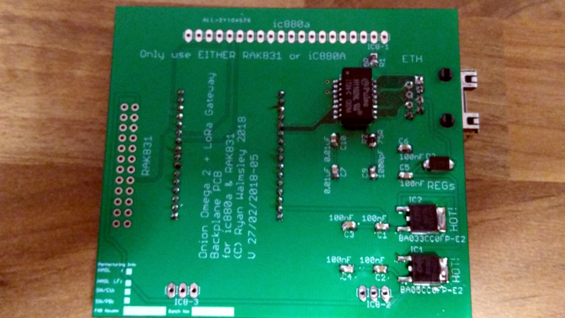
[Ryan Wamsley] has spent a lot of time over the past few months working on a new project, the Ultimate LoRa backplane. This is as its name suggests designed for LoRa wireless gateways, and packs in all the features he’d like to see in a LoRa expansion for the Nano Pi Duo.
His design features a three-terminal regulator, and in the quest for a bit more power efficiency he did what no doubt many of you will have done, and gave one of those little switching regulator modules in a three-terminal footprint a go. As part of his testing he inadvertently touched the regulator, and was instantly rewarded with a puff of smoke from his Nano Pi Duo. As it turned out, the regulator was susceptible to electrical noise, and had a fault condition in which its input voltage was routed directly to its output. As a result, a component in the single board computer received way more than its fair share, and burned out.
If there is a moral to be extracted from this story, it is to never fully trust a cheap drop-in module to behave exactly as its manufacturer claims. [Ryan]’s LoRa board lives to fight another day, but the smoke could so easily have come from more components.
So that’s the Fail of The Week part of this write-up complete, but it would be incomplete without the corresponding massive win that is [Ryan]’s LoRa board itself. Make sure to take a look at it, it’s a design into which a lot of attention to detail has been put.


If the idea of this article is to learn something from the mistakes or mishaps of others… then at least tell us what the name/number of the used regulator is! Otherwise it makes no sense to, or does it?
It was a Murata OKI-78SR specifically the OKI-78SR-5/1.5-W36H-C.
The model number is in the latest update at the bottom of the page. The fun part for me is that the same regulator I’m using to power some dataloging hardware in my car.
Agree, no info or pictures either here or there. :/
I imagine it applies to nearly any cost-engineered-to-the-bone module. This does make me feel less paranoid for having spent more time than I’d care to admit this morning compulsively heat-shrinking a cheap buck regulator module after hot gluing its trimmer in the desired position.
It was a Murata OKI-78SR specifically the OKI-78SR-5/1.5-W36H-C.
A fuse + zener at the output of a buck converter can save some if the converter goes nuts.
Common is to add say a SMAJ5.0 to a 5V rail. The problem is however that the zener is designed not to interfere at 5V+10%. So it will happily allow the voltage to become 5.5V. Next it needs some margin and then it needs a little extra voltage to get a significant current flowing. So… For the SMAJ5.0 the “max clamping voltage” is listed as 9.2V. Still quite enough to fry your 5V components.
Look up “crowbar circuit”
In short, when tripped by overvoltage sensing circuit, a scr will clamp the power line to ground and burn the fuse.
Switching regulator without the need of an external LC filter and some feedback? Does not seem like a good idea to me.
From the data sheet internal diagram it looks like it already has internal feedback and proper decoupling. If the regulator goes bonkers just by touching it, it is possible he touched the error amplifier input, so that the feedback signal was effectively summed/subtracted to anything his body was exposed to. This should not happen at all.
The module has an integrated LC filter on it… the datasheet even has a photo of it not sure how you missed that.
it is all integrated on the module and calling it an LC filter is a oversimplification
Then please elaborate because you lost me there… not that I’m a switching regulator expert but I’ve designed one or two circuits for them before.
My guess: the module has the regulator IC exposed. For some reason it uses very high value > 1Mohm feedback impedance. When you touch the feedback pins on the IC, the output voltage rises.
So it seems the real fail is the unnecessary use of too large feedback resistors. With 5 mA quiescent current, one can hardly claim its for power efficiency.
My guess as well.
Epoxying the feedback circuit entirely might also be a solution… It isn’t like Murata is low quality its just a design flaw.
Conformal coating it prevents the issue obviously. However when paying a premium then I expect it to be better than what I can implement myself which wasn’t the case.
Well I wouldn’t so much call it a flaw as a trade off as many switching regulators at least those with feedback circuits probably fail in exactly the same way… and honestly it shouldnt be suprising.
Low quality and flawed design doesn’t seem like a meaningful distinction to me. I don’t wanna epoxy my boards! That’s gross!
Could be worse. There was a guy called Draken that got infamous for glue-gunning NES’s (Nintendos).
sounds like a job for heat shrink!
Not to sound rude, but for the new board the DC-DC layout doesn’t look the best. It looks they are using an electrolytic capacitor for the DC-DC which makes me think it might be a MC34063 or similar variant as I think almost no DC-DC these days wants you to use those caps. They should look into the more recent DC-DCs available, some of them are around $1.5-2 once you add on the extra parts.
AP1509, Works out very cheap all in all.
As for electrolytics, well the datasheet says for cost effectiveness paired with ceramics for low ESR its a perfectly fine solution. The total cost for the inductor, chip and caps is under £1.50 which is half the price of the pre done module. And I can touch it without magic smoke :) (A perfect 5.2V on the oscilloscope too).
Sometimes a little extra power consumption and heat is worth dealing with in the name of reliability, in my opinion.
One technique I’ve seen in a lot of radios designed to run on 13.8v nominal (which can be as high as 16 to 18 volts even without a regulator fault) is to daisy-chain 2 or more linear regulators as needed. In the ones I’ve seen on my bench, the 13.8v is fed into a 7808, which then feeds the 8v electronics along with a 7805 that feeds all of the 5v electronics. Both regulators typically are mounted in such a way that they can use the cast aluminum chassis of the radio as a heat sink. On a PCB such as the one in the article this practice would be a bit less convenient (large heat sink required), but not unreasonable if reliability is a high priority.
Not to sound like a douche – but the fail of the week is ignoring ESD-regulations and touching around your bare PCBs.
I do that aswell and yes I know my ESD-band lies on the desk. But more than once I shocked myself when touching my door or something else. Not worth the risk.
Yes the article says it’s caused by change in the electric field and not through some discharge. But it’s the same deal. Don’t touch live components.
They are made within (or sometimes outside) of proper parameters and this component seems a bit susceptible to it.
This is a far reach, IMO – certainly not an ESD problem by any means. Besides, there are countless hobbyists that never really noticed any impact of ESD (especially given most modern diodes have ESD diodes either way), and most of them will never notice any.
And if we disregard the ESD comparison… Try touching the feedback resistor with a ground strap on, see how it goes.
Of all the many thousands of today’s manufactured components, a relatively small percentage are susceptible to ESD damage. Problem is, they all look the same from the outside so the safe way to manage components is to treat them all as though they are at risk.
some years ago i bought a stack of cheap $3 ubecs off of ebay. they are tiny and can source up to 3 amps. never had a problem with one.
I agree, also, it may be an assembly issue rather than a design issue. Sometimes stuff fail, one is not a statistically significant number.
I agree one is not, however two in a row. Without spending a lot of money I can’t do more testing.
“and had a fault condition in which its input voltage was routed directly to its output.” This is totally incorrect!
I even designed boards with DC/DC converts and have accidentally touched them while moving the board and they went up in smoke too. But that is user error NOT the parts fault. What you are saying is the same as you taking you finger and touching an audio amplifier circuit and hearing hiss and buzzing, then saying your op-amp has a “fault condition”
You cannot make claims like this when you add another component to the circuit “your body” when you touch it.
Hackaday, please don’t post stuff that is clearly a user design error.
Had a similar design failure on a very expensive commercial film processor (Read German engineered). For some reason they decided to use a socket for the regulator. The fumes were allowed into the electronics cabinet and over time corroded some connectors. Guess what happens when the ground pin floats on a three terminal regulator? Custom cpu with eprom was the only victim. (The Repair is another story)
T
Kindly review UL 840 and your necessary pollution degree rating for the application. It is not the regulators fault.
Use loads of these oki-78 smps, never had any problems, they’re great (found some cheaper alternatives on aliexpress though), touched with what ?
That’s not the only kind of failure to look out for. About 12 years ago, a commercial 5V and +/15V power supply’s -15V side failed in one of our equipment cabinets in our training lab. As a result, it took out 3 boards with loads of analog circuits. The boards were eventually scraped (took too long to diagnose & fix) at a total cost of around $20K. Since these were for the FAA, we had to have the failed power supply analyzed. After nearly 3 months (!) the manufacturer reported that it was “a normal failure of a 7815” !!! Whoops. The board designers “assumed” tracking power supplies, so if either side goes, they both go. Trouble is, that purchasing “missed” that salient spec because it was never specified by the hardware/systems engineer. I analyzed some of the failed boards on my own time and found that it was some op amps and some +5/-15V ADCs that failed. The op amps were JFET based. The ADCs were an older board revision and were replaced by +5V only versions.
Expect the unexpected (especially if you want to keep your customers happy).
Please don’t blame the switching regulator just because you don’t fully understand how it operates.
Kindly review the ESD tolerance for the component, before blaming the component.
If you need to protect the part from ESD then coat it. There are likely few ICs that will tolerate you touching them beyond 2kV on every pin.
If you need to protect output stages down stream then put some kind of limiting impedance along with a clamping element and some capacitance.
The only issue is, as far as I could see in the datasheet there’s no mention of it being ESD Sensitive.
However as most have stated to me already. Its not actually ESD to blame but the design of how switching modules work and changing the resistance.
If it’s not rated, then you have to assume it’s 0 not 30kV
I would hazard a guess the same thing could happen if you were to touch the exposed circuitry of a lot of discrete regulators, just like touching an amplifier and injecting hum. The regs I use, and have for quite a number of years with no problems at all, are those that are potted, with no exposed bits other than the 3 pins. So, I don’t see this as a failure of the reg so much as not a real good practice. A burst of hum from an amplifier is ok, but if it is a burst of “hum” from a power supply, that could be real bad! Just don’t poke fingers into the works if you want things to continue to operate correctly.
No part is fool proof. It just takes a event that was not test for to make smoke!
Never touch ESD sensitive devices without proper care
And how do you tell which are ESD sensitive?
MOSFETs in particular, and CMOS ICs built from them.
Guess it’s like a mining canary….
I know this is some 3 years after this article, but… This past weekend, I had the EXACT same issue as Ryan. And I found this article after figuring out what went wrong and doing a search to see if others reported anything similar. Mine happened to be a custom designed data acquisition board for a Musical Tesla Coil driver and it was an Atmega328PB micro (32 TQFP footprint), instead of the Nano Pi, but it was the exact same OKI-78SR-5/1.5-W36H-C regulator. It’s a really nice regulator, and I’ve used quite a few before. I will tell you that it was NOT an ESD issue.
I had just finished assembling the board and had just finished flashing some test code into the micro and was planning to let things run for a while. I was probing all of the board testpoint voltages to make sure everything looked right and accidentally touched the regulator board with my finger in the process. A few seconds later and there was a pop and the magic smoke came fizzing out of the micro. While analyzing what happened, I found that with only 1 or 2 seconds of “on” time, the micro would get so hot it would blister your finger.
I pulled the micro and found that there was a near dead short between the AVCC (analog supply input) and ground pins somewhere inside the micro (probably near the bulge on the top of the case where it had split open and lost its magic smoke). With the micro off the board, I experimented with observing the regulator output voltage while touching the regulator board with my finger, and you could easily make it rise and proportional to the pressure of your finger — in other words, the lower the resistance, the higher the voltage. I stopped at around 6.5 volts or so, as there were other 5V parts with absolute max ratings around 6.5V, but I think it would have gone all the way to the VIN of the regulator (which was 15V in my case).
It has all of the earmarks of affecting the error amplifier feedback voltage. Whether or not it’s a “design flaw” is debatable, but if you have a part that can’t stand more than about 5.5 volts (like these particular micros) and you’re using this regulator, then don’t touch the regulator! They do make an enclosed version. It cost a little more and was out of stock at the time, so I went with the open frame version, but I have since 3D printed my own enclosure that snaps over the top of the board. And I’m planning to put some copper shielding tape on that to help keep more noise out — I figure if it is that sensitive to my finger, it might be a little sensitive to the live Tesla Coil running close by.
I thought about adding some of the other protections mentioned in these comments, like the SMAJ5.0 and fuse, etc., but by the time you do all that, the cost starts making it impractical, as the micro doesn’t cost much more than all of those other pieces, and the repair time isn’t much different.
Anyway, I can 100% independently verify Ryan’s findings with this Murata regulator board.