PCBs are exceptionally cheap now, and that means everyone gets to experiment with the careful application of copper traces on a fiberglass substrate. For his Hackaday Prize entry, [Carl] is putting coils on a PCB. What can you do with that? Build a motor, obviously. This isn’t any motor, though: it’s a linear motor. If you’ve ever wanted a maglev train on a PCB, this is the project for you.
This project is a slight extension of [Carl]’s other PCB motor project, the aptly named PCB Motor. For this project, [Carl] whipped up a small, circular PCB with a few very small coils embedded inside. With the addition of a bearing, a few 3D printed parts, and a few magnets, [Carl] was able to create a brushless motor that’s also a PCB. Is it powerful enough to use in a quadcopter? Probably not quite yet.
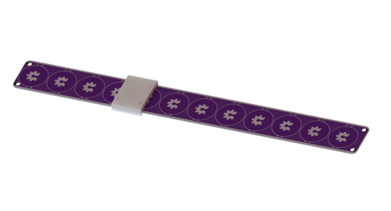
Like [Carl]’s earlier PCB motor, this linear PCB motor follows the same basic idea. The ‘track’, if you will, is simply a rectangular PCB loaded up with twelve coils, each of them using 5 mil space and trace, adding up to 140 turns. This is bigger than the coils used for the (circular) PCB motor, but that only means it can handle a bit more power.
As for the moving part of this motor, [Carl] is using a 3D printed slider with an N52 neodymium magnet embedded inside. All in all, it’s a simple device, but that’s not getting to the complexity of the drive circuit. We’re looking forward to the updates that will make this motor move, turning this into a great entry for The Hackaday Prize.


Oooh, now you “just” need to recapitulate this: https://hackaday.com/2015/08/18/ferrofluid-clock-is-a-work-of-art/
This project reminds me of an interesting voice coil design: https://micro.seas.harvard.edu/papers/ICRA14_Goldberg.pdf
When these sort of linear motors go to work:
https://www.rockwellautomation.com/en_IE/products/motion-control/overview.page?pagetitle=iTrak-Intelligent-Track-Systems&docid=d3a3ff0f88ff7932e26c34ab9b53ca90
I do automation for a living and I’ve been dying to work on one of these, it looks like you could do a lot of cool stuff with it.
See HP7225 plotter. PCB based Linear motors done in 80s.
do you have any pictures of this motor ?
There’s a picture of the overall plotter, here: http://www.hpmuseum.net/display_item.php?hw=72
But no photos of the motors themselves.
Takes me back John Honniball, used that type almost identical in 1980 or so to plot frequency response curves on adaptive filter equations I recall Kalman noise adaptive method at uni. Generated some really nice outputs, IIRC driven from an Led single line 9800 type series desktop glorified calculator which I think was the precursor to the HP85. Still have a 9872A with the paper feed rollers and a 7586B A0 vertical plotter with the Z8000 CPU and 150m roll feeder. Some good gear back then very appropriate for the work…
Sorry for delay replying, I’ve been offline past three days…
Full writeup on plotter in Feb 1979 HP Journal. (https://archive.org/details/hp_journal_1979-02) Actually a thin stamped steel stator on linear stepper motor, but with 0.002 inch resolution. Worth a looksee.
This is… uhh amazing. I don’t know how I never saw this.
Cool, What inductance do you get per coil?
According to the Hackaday.io page, “All design files for this project are also open source.” However, this does not appear to be the case. No design files of any kind are available at present.
While I acknowledge that many Hackaday.io project pages are works-in-progress, it strikes me as improper to go so far as to submit your project for contests and discussion, bearing twelve copies of the OSHW logo no less, with no tangible effort made towards participating in the open source community.
Haha sorry for that! I have received the pcbs last Thursday and then some time for testing .. i have just uploaded the gerber files on my project page!
Thanks!
Can you put several strips next to each other and get some XY movement?
Yes, you can. https://hackaday.com/2018/05/22/smiling-robot-moves-without-wires/ (sorry for reporting, that button finally got even me, old HD veteran).
A PCB railgun! Sweet!
Nope, but it could be used as weak coilgun.
They might be able to speed something up considerably if the print a circular rail…? maybe…?
Interesting. Get two of these, offset them by a quarter wavelength, and you should have a relative encoder, I think.
Yeah good observation John Smith, much like the ball bearing reluctance encoders used on machine tools some 20 years ago. I had occasion to investigate one of these, had 3 plugin boards of analogue and ttl chips and led readouts but, position volatile. Battery backup an option. The coils were on the moving tool parts with a long thermoset tube of precise steel ball bearings fixed on the machine bed. Even back then the electronics seemed way too big for what it needed to do like a PC ATX case. Standard unit resolution was good to 0.001mm with claimed accuracy of around +-0.0004mm which wasnt quite as good as the other scales (glass quadrature type) by Sony and Heidenhain, iirc twice better ie +-0.0002 though I think that was already a higher grade product…
So in this case use the fixed coils as the set reader along the whole bed measurement length and suitable ‘magnetic’ slugs only on the moving parts simplifies wiring connections as only on the boards. Encoding would work on coupling and phase modulation/detection along length as counted and change of direction interpreted similarly though machine jitter potential would suggest high frequency operation more reliable. There would be a couple of niggles to address re noise, calibration and thermal compensation but, really straightforward stuff but, outcome would be quite robust. When I looked at this 20 or so years back in writing up reports on alternate methods there were heaps of patents and all would have expired by now, so it’s wide open slather – maybe already done ;-)
Cheers.
Shall we use permanent ceramic magnet instead of neodymium magnet for linear motor
Lay out a bunch of these in a 2D pattern and maybe get a way to make a chess or miniatures gaming table.
Eric Laithwaite would be pleased, he championed linear motors and extensions as well as exploring gyroscopes.
https://m.youtube.com/watch?v=vauFEgRdYks
Sound improves few secs in.
With multilayer boards these days such as for multipolar configurations a sizable amount of force can be expressed in a physical design very efficient to manufacture and can be bent or twisted to sort of hide where needed. For example novel toys and aids for the handicapped…
Nice to see a post on this and looking forward to diverse comments, thanks
Fit these to LEGO train tracks to eliminate the onboard motors.
or implement Lego maglev, nice thought thou. If the PO can submit some cost calculations/realizations then I might actually think of implementing one, providing it does not break a bank. I have some old track sets from 80’s which migh prove to be usefull for something like this.
The way i remember the large linear motors from the big PCB drilling machines, they always had a bed of stationary permanent magnets and the coil was on the moving part. Guess in that application that has to do with the weight of these magnet beds compared to the coil. If you want your axis to accelerate at 4g, it’s probably the smarter way to arrange it like that.
How about using two of these coil strips working on top of each other? I think the modern large DC engines work that way, i.e. there is no permanent magnets involved at all. How about embed small ferrite/ceramic studs on the PCB to boost the field of the coils?
Cool true and maybe a great way to fabricate the Star Trek sliding doors too ie. Linear actuators in floor and top above doors and maybe top along sides too – heck with the right select of frequencies and with selection of in-wall air dampers might give the same sound pattern matching the door’s decel/accel rates too :-)
If you want the sound of the Star Trek doors: Grab a letter sized envelope and side a letter sized piece of paper in and out. That’s what the folie artists used
Think of two of these used together would make for an XY gantry, given if you have enough force and decent accuracy, it could replace CoreXY.
This is a really nice project ! I would love to see more project like this one on hackaday ! I am looking forward to the updates !
Seems like you could make a kick-ass modular RC race/train/robot toy with this.