Understanding A MOSFET Mixer

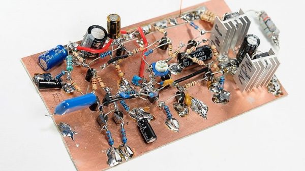
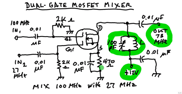
A mixer takes two signals and mixes them together. The resulting output is usually both frequencies, plus their sum and their difference. For example, if you feed a 5 MHz signal and a 20 MHz signal, you’d get outputs at 5 MHz, 15 MHz, 20 MHz, and 25 MHz. In a balanced mixer, the original frequencies cancel out, although not all mixers do that or, at least, don’t do it perfectly. [W1GV] has a video that explains the design of a mixer with a dual gate MOSFET, that you can see below.

The dual gate MOSFET is nearly ideal for this application with two separate gates that have effectively infinite input impedance. [Stan] takes you through the basic circuit and explains the operation in whiteboard fashion.

Continue reading “Understanding A MOSFET Mixer”

A Close Eye On Power Exposes Private Keys

Hardware wallets are devices used exclusively to store the highly sensitive cryptographic information that authenticates cryptocurrency transactions. They are useful if one is worried about the compromise of a general purpose computer leading to the loss of such secrets (and thus loss of the funds the secrets identify). The idea is to move the critical data away from a more vulnerable network-connected machine and onto a device without a network connection that is unable to run other software. When designing a security focused hardware devices like hardware wallets it’s important to consider what threats need to be protected against. More sophisticated threats warrant more sophisticated defenses and at the extreme end these precautions can become highly involved. In 2015 when [Jochen] took a look around his TREZOR hardware wallet he discovered that maybe all the precautions hadn’t been considered.

Continue reading “A Close Eye On Power Exposes Private Keys”

A Guide To Audio Amps For Radio Builders

For hams who build their own radios, mastering the black art of radio frequency electronics is a necessary first step to getting on the air. But if voice transmissions are a goal, some level of mastery of the audio frequency side of the equation is needed as well. If your signal is clipped and distorted, the ham on the other side will have trouble hearing you, and if your receive audio is poor, good luck digging a weak signal out of the weeds.

Hams often give short shrift to the audio in their homebrew transceivers, and [Vasily Ivanenko] wants to change that with this comprehensive guide to audio amplifiers for the ham. He knows whereof he speaks; one of his other hobbies is jazz guitar and amplifiers, and it really shows in the variety of amps he discusses and the theory behind them. He describes a number of amps that perform well and are easy to build. Most of them are based on discrete transistors — many, many transistors — but he does provide some op amp designs and even a design for the venerable LM386, which he generally decries as the easy way out unless it’s optimized. He also goes into a great deal of detail on building AF oscillators and good filters with low harmonics for testing amps. We especially like the tip about using the FFT function of an oscilloscope and a signal generator to estimate total harmonic distortion.

The whole article is really worth a read, and applying some of these tips will help everyone do a better job designing audio amps, not just the hams. And if building amps from discrete transistors has you baffled, start with the basics: [Jenny]’s excellent Biasing That Transistor series.

[via Dangerous Prototypes]

Tricking A Vintage Clock Chip Into Working On 50-Hz Power

Thanks to microcontrollers, RTC modules, and a plethora of cheap and interesting display options, digital clock projects have become pretty easy. Choose to base a clock build around a chip sporting a date code from the late 70s, though, and your build is bound to be more than run-of-the-mill.

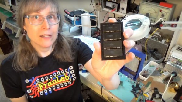
This is the boat that [Fran Blanche] finds herself in with one of her ongoing projects. The chip in question is a Mostek MK50250 digital alarm clock chip, and her first hurdle was find a way to run the clock on 50 Hertz with North American 60-Hertz power. The reason for this is a lesson in the compromises engineers sometimes have to make during the design process, and how that sometimes leads to false assumptions. It seems that the Mostek designers assumed that a 24-hour display would only ever be needed in locales where the line frequency is 50 Hz. [Fran], however, wants military time at 60 Hz, so she came up with a circuit to fool the chip. It uses a 4017 decade counter to divide the 60-Hz signal by 10, and uses the 6-Hz output to turn on a transistor that pulls the 60-Hz output low for one pulse. The result is one dropped pulse out of every six, which gives the Mostek the 50-Hz signal it needs. Sure, the pulse chain is asymmetric, but the chip won’t care, and [Fran] gets the clock she wants. Pretty clever.

[Fran] has been teasing this clock build for a while, and we’re keen to see what it looks like. We hope she’ll be using these outsized not-quite-a-light-pipe LED displays or something similar.

Continue reading “Tricking A Vintage Clock Chip Into Working On 50-Hz Power”

PCBs As Linear Motors

PCBs are exceptionally cheap now, and that means everyone gets to experiment with the careful application of copper traces on a fiberglass substrate. For his Hackaday Prize entry, [Carl] is putting coils on a PCB. What can you do with that? Build a motor, obviously. This isn’t any motor, though: it’s a linear motor. If you’ve ever wanted a maglev train on a PCB, this is the project for you.

This project is a slight extension of [Carl]’s other PCB motor project, the aptly named PCB Motor. For this project, [Carl] whipped up a small, circular PCB with a few very small coils embedded inside. With the addition of a bearing, a few 3D printed parts, and a few magnets, [Carl] was able to create a brushless motor that’s also a PCB. Is it powerful enough to use in a quadcopter? Probably not quite yet.

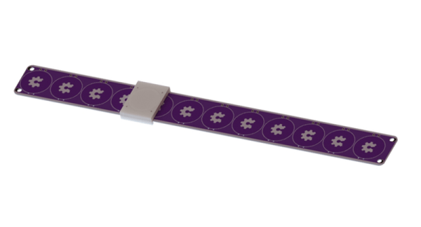
Like [Carl]’s earlier PCB motor, this linear PCB motor follows the same basic idea. The ‘track’, if you will, is simply a rectangular PCB loaded up with twelve coils, each of them using 5 mil space and trace, adding up to 140 turns. This is bigger than the coils used for the (circular) PCB motor, but that only means it can handle a bit more power.

As for the moving part of this motor, [Carl] is using a 3D printed slider with an N52 neodymium magnet embedded inside. All in all, it’s a simple device, but that’s not getting to the complexity of the drive circuit. We’re looking forward to the updates that will make this motor move, turning this into a great entry for The Hackaday Prize.

Ask Hackaday: What Color Are Your PCBs?

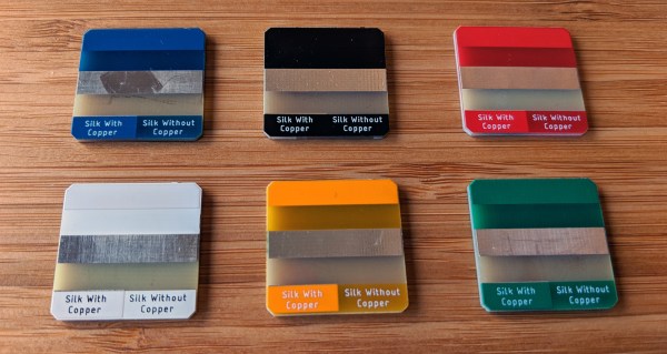
A decade ago, buying a custom-printed circuit board meant paying a fortune and possibly even using a board house’s proprietary software to design the PCB. Now, we all have powerful, independent tools to design circuit boards, and there are a hundred factories in China that will take your Gerbers and send you ten copies of your board for pennies per square inch. We are living in a golden age of printed circuit boards, and they come in a rainbow of colors. This raises the question: which color soldermask is most popular, which is most desirable, and why? Seeed Studio, a Chinese PCB house, recently ran a poll on the most popular colors of soldermask. This was compared to their actual sales data. Which PCB color is the most popular? It depends on who you ask, and how you ask it.
Continue reading “Ask Hackaday: What Color Are Your PCBs?”

Bike-Driven Scarf Knitter Is An Accessory To Warmth

Despite all our technological achievements, humans still spend a lot of time waiting around for trains. Add a stiff winter breeze to the injury of commuting, and you’ve got a classic recipe for misery. [George Barratt-Jones] decided to inject some warmth into this scene by inviting people to knit a free scarf for themselves by riding a bike.

All a person has to do is ride the Cyclo-Knitter for five minutes and marvel at their handiwork. By the time the scarf is finished, they’ve cycled past being cold, and they have something to hold in the warmth. Cyclo-Knitter is essentially an Addi Express knitting machine being belt-driven by a stationary bike. Power is transferred from the bike through large, handmade wooden gears using old bike tire inner tubes as belts. [George] built a wooden tower to hold the machine and give the growing scarf a protected space to dangle.

We love the utility of this project as much as the joy it inspires in everyone who tries it. Check out their scarves and their reactions after the break. We haven’t seen people this happy to see something they weren’t expecting since that billboard that kills Zika mosquitoes.

Continue reading “Bike-Driven Scarf Knitter Is An Accessory To Warmth”