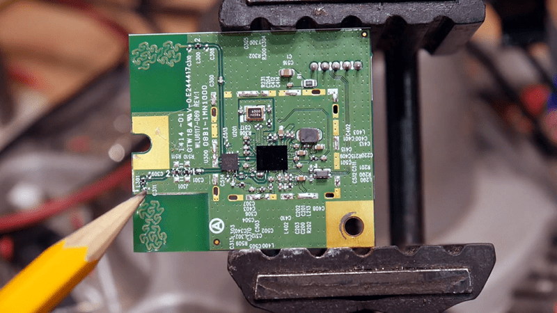
[IMSAI Guy] tore apart a device with a wireless network card and decided to investigate what was under the metal can. You can see the video of his examination below. Overall, it was fairly unremarkable, but one thing that was interesting was its use of an antenna on the PCB that uses a fractal design.
You probably know fractals are “self-similar” in that they are patterns made of smaller identical patterns. The old joke is that the B. in Benoit B. Mandelbrot (the guy who coined the term fractal) stands for Benoit B. Mandelbrot. You can think of it as akin to recursion in software. Antennas made with fractal patterns have some unusual and useful properties.
These antennas were developed in 1988 by [Nathan Cohen] and published in 1995, even though log periodic antennas were already in use that used unrecognized fractal properties. Like log periodics, but unlike most other antennas, fractal antennas can be very broadband. The reason is that the fractal structure creates virtual combinations of capacitors and inductors that provide many different resonances.
Of course, the design of these can be challenging and is often done via simulation. There are also detractors that say fractal antennas don’t really work better. If you want to see something practical check out this thesis from several students at Nirma University which uses simulation to design such an antenna and look at its performance.
We’ve talked about fractals before if you want a bit of history. This looked a bit similar to another fractal antenna found in a scale, of all places.


2/4ghz WLAN board. BRCM CSP SoC. https://wikidevi.com/wiki/Askey_WLU6117-D69
Fractal LEDS.
Self-sealing stem bolts.
I wish I could upvote this.
Are you selling any? I need a whole bunch of them ASAP.
Fractal antennas are quite nice, never used them on anything but its a nice design
also, i should note that most of what he says besides the antenna description is a bit off
Not a fractal antenna. It’s just an antenna with squigglies to take up less space. (Like a whip antenna can have a loading coil on the bottom to make it effectively longer — the repeating coils of wire do not make it a fractal antenna.) A key aspect of fractal antennas is that their motif repeats over two or more scale sizes. There is only one scale in this antenna. And in the loaded whip antenna.
This is a Gosper Curve. It is most certainly a type of fractal. It’s of the category of space filling fractal lines, and is related to the rectangular Hilbert Curve fractal that many 3d printer enthusiasts are familiar with.
https://en.wikipedia.org/wiki/Gosper_curve
A Gosper curve is not a fractal by Mandelbrot’s definition. A fractal is a set for which the Hausdorff dimension strictly exceeds the topological dimension, but in the case of space-filling curves, the dimension is equal to the topological dimension, not greater than it.
What are you talking about? A Gosper curve has fractional dimension, which is Mandelbrot’s original definition.
Just because one didn’t run the L-system infinite iterations doesn’t mean it’s not fractal.
“There is some disagreement amongst authorities about how the concept of a fractal should be formally defined. Mandelbrot himself summarized it as “beautiful, damn hard, increasingly useful. That’s fractals.”[13] More formally, in 1982 Mandelbrot stated that “A fractal is by definition a set for which the Hausdorff-Besicovitch dimension strictly exceeds the topological dimension.”[14] Later, seeing this as too restrictive, he simplified and expanded the definition to: “A fractal is a shape made of parts similar to the whole in some way.”[15] Still later, Mandelbrot settled on this use of the language: “…to use fractal without a pedantic definition, to use fractal dimension as a generic term applicable to all the variants.”[16]” — wikipedia link given above.
Fractals are not typically self similar
http://www.3blue1brown.com/videos/2017/5/26/fractals-are-typically-not-self-similar
I always thought of a fractal as a shape with an infinitely long circumference.
Fractals are not magic. In the context of antenna design they are almost universally worse than a simple space-filling curve like a simple back and forth meander line. And any space filling curve is necessarily a significantly worse antenna than a simple planar inverted-F.
The property that really matter’s is not self-similarity but weather or not the antenna/dielectric pattern is mutually complementary (ie, equal metal and dielectric, if you switch one for the other it looks the same). That property can improve the bandwidth of the space filling curve (be it a fractal or rectangular meander line) that is sacrificed when making it so small.
When you see a fractal antenna you know two things: 1. They ran out of space. 2. It’s not going to work very well.
A rather silly place to use them. Geometrically self similar fractals give the corresponding property of self-similar impedance versus frequency. That is to say, wide bandwidth.
An extremely simple yet effective example: the bowtie antenna. This exhibits the useful fractal property (self similarity, not even at discrete geometric scales but by continuous scaling, in fact), and gives quite nice bandwidth and impedance characteristics, despite being planar.
You don’t get any advantage using an “electrically small” fractal, at two narrow bands (2.45 and 5GHz, I guess). You just end up wasting space, space that is ever-more precious in these days of IoT.
The nice thing about the common inverted-F is, its simple geometry can be tuned automatically by the simulator. The elements can be built in stepped and finned sections, giving as many passbands as desired — since only two are needed here, that’s even better!
Remember, there’s no need to receive frequencies you’re not interested in. Indeed, you want to avoid anything that might show up as images or aliasing. As I repeat frequently: only use the bandwidth you need!
The even nicer thing with inverted f is that you can tune them with a scalpel.
Consider a fractal antenna to be a series of capacitative stubs and/or distributed inductive components and it starts to make a lot more sense. It’s just another shortened antenna with a loading scheme.
Don’t misunderstand, it’s a clever loading scheme, and it may have a slightly better bandwidth than other loading methods. But because it is a loaded antenna, the gain will always be less than a full size version of the same antenna. In most shortened circuit board applications the gain is actually worse than isotropic. In those cases we do not discuss gain, we discuss “efficiency.”
By the way, I know this because I remember discussions on usenet back in the early 1990s where Chip tried to convince several other recognized ham radio antenna experts that his antenna invention was really something different.
The bottom line is that you can shorten an antenna with loading coils and capacitative stubs, But as you do so, the bandwidth of that antenna will decrease, voltage and current nodes will increase, and thus losses will go up. Note that if the bandwidth does not decrease, then you’re losing energy somewhere else. The bandwidth of a fractal antenna may decrease at a very slightly lower rate than a straight loaded antenna, but that may not result in a significantly better antenna because losses will also be distributed, TANSTAAFL.
I don’t think the two antennas are placed to be two directional, seeing the squiggles already make the elements point in various (2-dimensional) directions.
And I think the difference between the filter components between the two of them has more significance than he gives it credit.
There is no trick to beat a properly cut, aimed, and polarized half wave dipole; sure you can directionalize but everything else is a compromise to try to get close to that 1/2 wave dipole performance within your engineering limitation whatever that is.
That thesis is severely lacking in any conclusion other than “hey it works”. It’s just a bunch of pictures with misspelled captions and charts that have no context. I realize it was probably just a paper for a BS but seven people are on that paper and that’s all they could do? I was expected to produce much more content just for weekly lab reports in freshman level classes.
I’d love to have someone adapt these 2.4 GHz antennas for the HF ham bands, perhaps by finding a way to create fractal cuts in four-foot-wide strips of attic foil from sources such as the one below. They might make excellent attic antennas.
https://atticfoil.com
Itsa Gosper fractal antenna. The length allows more than one current maxima, which gives some gain in this small height. The ohmic loss of the length is obviously trivial.
There is no controversy on fractal antennas. You guys just like recalling incorrect bits from years ago. The fact that you see them being used says it all. Thanks Al and best to you..
I am swamped meeting orders here an will not respond to any further comments.
Its a fractal antenna because its apparent length is dependent on the frequency applied to it. Its really useful is you need frequency agility which I would assume is the case if this device is using diversity antennas at 2.4 GHz and 5 GHz. The trick is that the geometry allows the 2.4 Ghz frequency to follow the full length of the path and the 5 Ghz frequency bridges across certain areas of the path to get the ideal wavelength for each band. The design does not necessarily have to follow the mathematical rules of a fractal. It is just that the geometry looks an awful lot like a fractal.