
The first program anyone writes for a microcontroller is the blinking LED which involves toggling a general-purpose input/output (GPIO) on and off. Consequently, the same GPIO can be used to read digital bits as well. A traditional microcontroller like the 8051 is available in DIP packages ranging from 20 pins to 40 pins. Some trade the number of GPIOs for compactness while other devices offer a larger number of GPIOs at the cost of complexity in fitting the part into your design. In this article, we take a quick look at applications that require a larger number of GPIOs and traditional solutions for the problem.
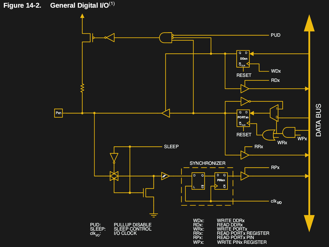 A GPIO is a generic pin on an integrated circuit or computer board whose behavior, including whether it is an input or output pin, is controllable by the user at runtime. See the internal diagram of the GPIO circuit for the ATmega328 for reference.
Simply put, each GPIO has a latch connected to a drive circuit with transistors for the output part and another latch for the input part. In the case of the ATmega328, there is a direction register as well, whereas, in the case of the 8051, the output register serves as the direction register where writing a 1 to it sets it in output mode.
The important thing to note here is that since all the circuits are on the same piece of silicon, the operations are relatively fast. Having all the latches and registers on the same bus means it takes just one instruction to write or read a byte from any GPIO register.
When Do You Need More GPIOs?
 What could you possibly need a large number of GPIOs for? Let’s talk about LED sign boards. Even something small like 32 x 32 pixels requires a minimum of 1,024 GPIOs if you want to drive each LED directly. RGB LEDs are essentially three LEDs which means three times the IO requirement. Now imagine driving enough of these panels to fill a wall. Clearly, this demands simplification.
Then there are applications that require reading bits like in the case of the keyboard. In the case of the Hackaday Belgrade Badge, the keyboard has 55 buttons but you can imagine the complexity for a 101 button keyboard. I recently did a project where I had to read 120 digital sensors at the same time and the PCB real-estate available was pretty limited.
So how do we get there? There are a number of ways the GPIOs count can be extended, though some applications can do without dedicated I/Os. The important thing is to understand the pros and cons of each approach to find the best fit for your next project.
Matrix scanning
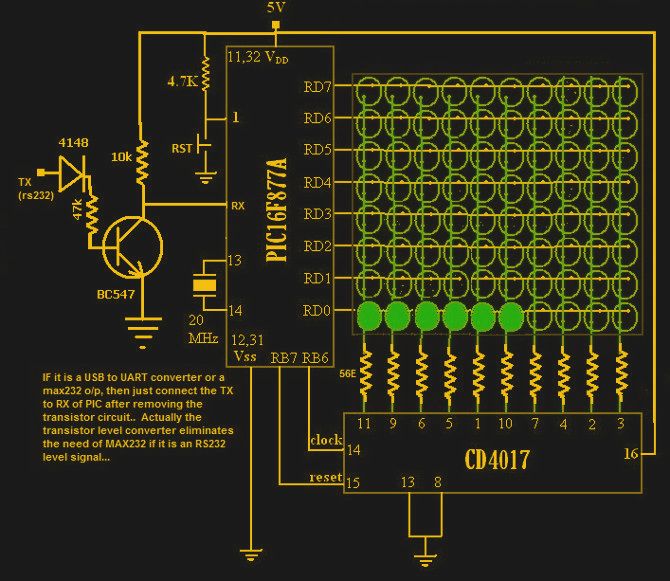 Matrix scanning involves using a multiplexer to ‘emulate’ a larger number of I/Os. A good case for matrix scanning is the LED dot matrix. Human persistence of vision can make it appear as if all the LEDs are lit up for longer than they actually are. The arrangement is called a “scanning” display because LEDs illuminate one column at at time and all the LEDs in a row have their cathodes tied together to a single IO.
The columns can be driven by GPIO pins, of course, but since they are simply advancing through the columns one at a time, it often makes sense to connect them to the output of a counter chip, say a CD4017 if you’ve only got ten columns. For each column, the microcontroller turns on the relevant I/O to display a pattern and then clocks the counter to select the next column after which the process repeats.
A matrix scanning keyboard can be made the same way, with the GPIO pins set in input mode. As each column is pulled high, the GPIOs on the rows can sense which buttons in that column have been pressed. To accurately detect multiple presses, a diode per button is required.
Matrix scanning can be a simple solution to mid-sized GPIO requirements, but even it has its limitations. Take the example of driving a 32 x 32 array of LEDs again: it requires at least 32 for the rows plus a clock and reset to drive an external counter for the columns. Many rows simply means many GPIOs. And the more columns you have, the larger the time between refreshes of any individual pixel grows. But there is more than one way to skin the proverbial cat.
Shift Registers
A simple way of adding I/O to microcontrollers is the use of shift registers. Chips like the 74HC595 and 74HC4094 are commonly used to add outputs. On the input side, the CD4021BC and the SN74HC165N are both classic chips and there are naturally tutorials for both online: Arduino’s 4021 tutorial and Adafruit’s HC165N tutorial, for instance.
The SPI bus works essentially like a shift register, or conversely, shift registers can be easily driven by your microcontroller’s onboard SPI hardware. This means that the clocking and data shifting can be done using a dedicated hardware peripheral instead of the bit bang software routines shown above.


Recall our above discussion of matrix scanning to drive LEDs. The number of GPIO pins grew as the number of rows. Using a shift register for the rows would lighten the GPIO burden significantly. It’s perhaps no surprise that the LED matrix panels available in the market employ shift registers to read in their row data. As a bonus, chaining the row shift registers allows panels to be simply connected together.
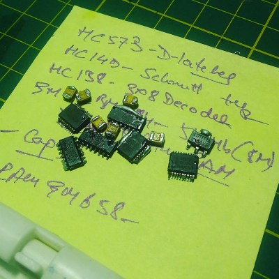
If you’d like to display animations, this means that it will become necessary to shift data through them fast enough to achieve a particular frame rate. The images above show such a matrix display taken apart and it uses the TLC5958 equivalent as the data element. The 74HC245 is used as the driving element and the 74HC138 as a decoder for the address line. Check out this TI App note for more details (PDF).
 Multiplexers and shift registers offer an elegant solution to adding pins to a controller. Daisy-chained shift registers not only simplify PCB routing but also reduce signal-to-signal skew and jitter since all latches are controlled by the same output enable signal.
The downside is that to read or write to the furthest chip, the data must be cycled through all the chips in the chain. Anyone who has had any experience with the chainable LED driver P9813 or the more famous WS2812 knows that sending 24-bits of color data per LED over a serial line introduces visible latency.
(Side note: I also found similar chips in an old DVR at our office. Anyone find similar useful chips in old equipment?)
Other IO Expander Chips
SPI- and I2C-based IO expanders are yet another method for adding I/O to a low-cost microcontroller. The Microchip MCP23S17 and MCP23017 are popular options, and can be configured as output or input just like a local GPIO. Additionally, these chips provide features such as interrupts that can come in handy when configured as input ports.
Such devices, however, are not without drawbacks as the cost of the expanders can be an overhead. Also, these chips are not as cheap as the 74HC595 shift register, nor are they as fast as on-chip GPIO. They are also most often aimed at medium-sized IO problems.
Microcontrollers
Another possibility when you need more GPIO pins is to simply use more microcontrollers. This approach is more like designing sub-modules: for example, using a dedicated microcontroller for the keyboard control and using another for the display, or even for a fraction of the display. Modularity can help in reducing time-to-market, and is typical for many products such as digital power supplies, oscilloscopes and the like. In the end, all the sub-processors must talk to a master processor that controls the system as a whole.
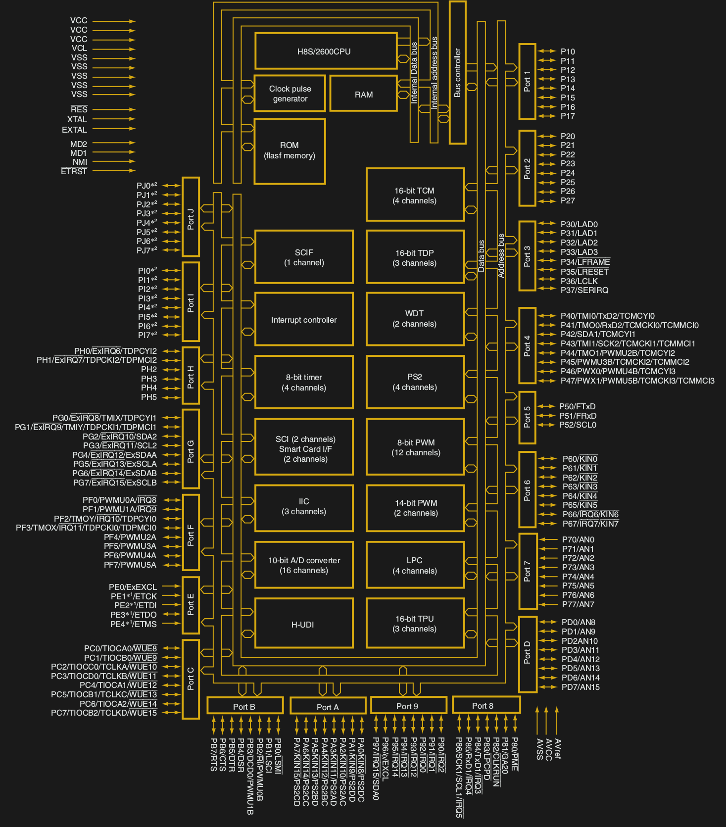 Piling up sub-systems may be fast and flexible, but the cost of multiple microprocessors and the required PCB space may not work for some projects. Its worth considering this cost against the cost of using a single microcontroller with high I/O pin counts. Controllers such as the DF2117VBG20V from Renesas come in a 176-pin LFBGA package and feature 128 I/Os. (Wow!) The catch is that the PCB complexity can be a routing nightmare even on a four-layer board, and assembling and testing is complicated by the small feature size required.
FPGAs and CPLDs are perhaps the ‘go-to solution’ for high-IO-count applications. Writing complete projects in Verilog/VHDL is always a tough job, but the adoption of software processors has eased things a lot. FPGAs can also be a bit more pricey and adding configuration EEPROM to the mix does not make things easier. That’s where CPLDs shine.
Where do you go from here?
The selection of a design method depends greatly on the application. Today there are dedicated chips for almost everything you could dream of. However, there is always the chance of landing a client with a quirky requirement. The constraints on a hobby project are clearly different from those on a multi-thousand unit commercial product.
What do you do when you need a lot of GPIOs? What are the particular advantages and drawbacks of those solutions? We would love to hear about them.


This is one of those Engineering areas you can get very inventive at. Great article
“The Microchip MCP230S17 and MCP23017 are popular options, and can be configured as output or input just like a local GPIO.”
I think it is MCP23S17 and MCP23017. No 0 for SPI version.
Look like you are correct. I’ll touch that up in the article. Thanks!
Never heard of these chips, but I’ve seen boards from customers use PCF… and PCA… I2C I/O expanders.
MCP23017 is pretty good stuff. Of course the tradeoff is slowness compared to native GPIO, but it has latched input change flags, pullups, outputs configurable as push-pull active high or low or open-drain, and can run up to 1.7MHz I2C bus speed. The SPI can be faster, of course, but the I2C version is handy if you wanted to use your hardware SPI for other things. I’ve been selling a board with the MCP23017 for half a dozen years and it’s still pretty popular.
hehe, I’m preparing to start selling a small MCP23017 breakout =)
The first rule of getting more I/O for a microcontroller is to select a microcontroller with more I/O pins.
When you max that out, you start looking at port expanders and stuff.
Smaller microcontrollers sometimes have higher per-pin current drive capabilities. (e.g. Microchip’s 40-pin and smaller PICs support 25mA on every pin, but their 64-pin and larger PICs only support 4 or 8 mA on some pins).
A larger microcontroller with an external current amplifier IC might not be cheaper than just using an I/O expander in the first place.
It’s certainly not the first rule when it comes to BOM costs, often it is much cheaper to use an IO expander than to upgrade the MCU. Also when you upgrade the MCU, you will often also end up paying for a whole bunch more stuff that you didn’t need. You will have a much more complex internal clock tree that might not be compatible. And if all your extra IO is concentrated in one corner of the board, then an IO expander will make your routing much simpler.
So ATTiny10 can drive a few 1W LED while an ATMega2560 can’t handle more than a dozen regular LEDs.
lol
Total nightmare: mixing buses to increase GPIOs.
Example: Controlling SPI chip-selects via I2C GPIO expanders. Congrats, you just capped a high-speed bus (SPI) at a painfully slow speed (I2C).
Several of my company’s products do this, and they constantly complain about SPI performance, yet still keep designing the same way.
/facepalm #TheyDidn’tListen
A single ADC pin can read a large switch matrix if you chose your resistor values well.
A shift register can also simplify coding on some MCUs that have lots of IO pins but don’t have a port with 8 contiguous unused IO. For example, if you are using the hardware UART on an ATMega328p, that ties up 2 pins on port D. And if you use an external crystal oscillator, that ties up 2 pins on port B. So if you want to light up the segments on a 7-segment LED display, writing to the SPI port hooked up to a shift register is easier to code than splitting the bits across multiple ports.
This article comes at just the right time for me, redesigning my digital in / out matrix for my project on Hackaday.io! (Currently using MCP23S08 / MCP23008).
Thanks Hackaday!
I recently discovered cheap Chinese ICs, TM1637 and TM1638, that offer led multiplexing with built-in keypad scanning. They use a two wire protocol that is very similar to I2C.
Yes! Me2
Ditto.
I recently finished a small TM1638 library: https://github.com/nerdralph/nerdralph/tree/master/TM1638NR
The TM1637 looks like a much cheaper option than the Max7219, though it will only do a matrix of up to 6×8 vs 8×8 for the 7219.
I still like ‘595 shift registers since they are so cheap (2-3c ea), and are useful for more than just driving LEDs.
Adafruit’s Cricket robot control boards are based on a microcontroller running their “seesaw” program. They also sell a breakout board that’s just a ATSAMD09 running seesaw.
And yet charlieplexing is somehow missing from this great article ;-)
Drive n*(n-1) LED from n pins!
https://en.wikipedia.org/wiki/Charlieplexing
How many STM32 blue pills can you hang off a CAN bus, that could give you a lot of I/O for very little money.
There are shift registers which can drive high power directly. Using them you can spare not only IO pins but also (some of) the driver electronics. Some of them also have some back-EMF protection so they can be used to drive even mechanical relays or mini-motors. I have even seen the datasheet of one that has a built-in flyback diode.
An example of a high power shift register is the TPIC6B595.
The latching feature is also important: all output is updated at once (on a separate clock) so there is no transient on the output while bits are being shifted in.
Understand all the details in the datasheets and use them with care!
Once I had to implement a LED based multiple 7 segment UI with shift registers and the lack of latching capability made it a nightmare and very hard to count all the timing so that there is no vibration in the result. With clever exact switching of OE using PWM and updating the bits while PWM is off (eg use inverted PWM that turns off at overflow and impelement shifting out in the overflow handler) it was possible to create totally correct timing at the end.
Not even a passing mention of Charlieplexing? Shame on you HAD. ;)
Personally, I was waiting for the reference to FPGA’s as a way to implement all these options.
Including changing the microcontroller.
Nothing on just common muxes? They are amazing to use to get more analog signals for example. Depending on the mux size, it will cost you a few more I/Os than a shift register, compared to what you get, but most often you’ll get severeal analog, bi-directional signals for your usage. And with some smart combination of muxes and shift registers, you can expand your analog I/Os a lot!
For high current, low speed outputs, nothing beats the cost, availability and expandability of a set of 74hc595s and uln2003s
Hi, I assume some of you might be interested in EMF protection materials for some projects, there are plenty of choice, and even magnetic shielding materials: http://emfclothing.com
I wonder who can recommend a microcontroller with a high number of IOs.
But each pin has to be
Settable to Input
Settable to Output
Internal Pullup programmable
Internal pull down programmable
or is an FPGA the only solution?