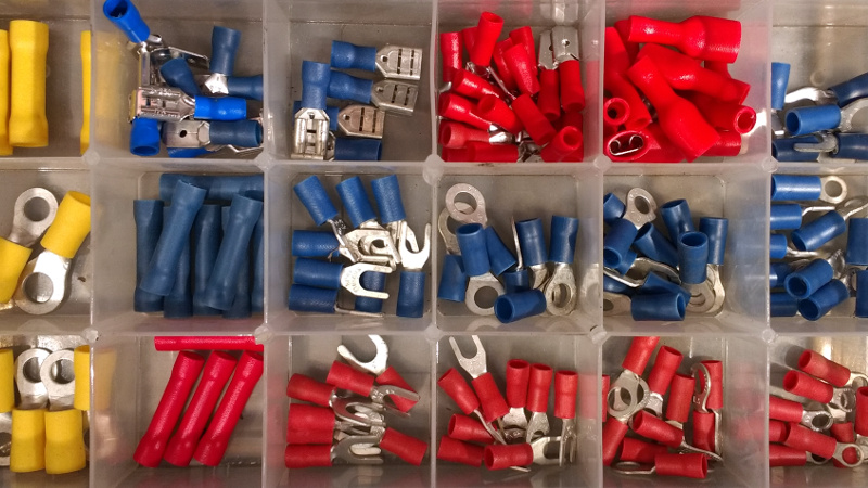
Almost every project of mine from the last quarter century, if it has contained any wiring, has featured somewhere at least one crimp connector. There are a multiplicity of different types of crimp, but in this case I am referring to the ubiquitous variety with a red, blue, or yellow coloured plastic sleeve denoting the wire size they are designed for. They provide a physically robust and electrically sound connection that is resistant to wire fatigue due to vibration, and that can carry hefty currents at high voltages without any problems.
You might expect this to now head off into the detail of crimp connection, but my colleague Dan has already detailed what makes a good or a bad crimp. Instead recently my constant searches for weird and wonderful things to review for your entertainment led me to a new crimp tool, and thence to a curiosity about the effectiveness of different styles of tool. So I’m going to evaluate the three different crimping methods available to me, namely my shiny new ratchet crimp pliers, my aged simple crimp pliers, and for comparison an ordinary pair of pliers. I’ll take a look at the physical strength of each crimping method followed by its electrical effectiveness, but first it’s worth looking at the tools themselves.
Laying Out the Tools
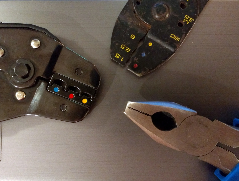
There is little to say about the set of pliers other than that they are a perfectly ordinary set of pliers — sometimes called Lineman’s Pliers — that happens to be on my bench so I will call them Bench Pliers. You almost certainly have a very similar set.
My Simple Crimp Pliers were bought sometime in the 1990s from an automotive superstore, and they’re type of multipurpose auto electrical tool that yet again many of you probably have. They have many functions, but those that interest us are the shaped receptacles with the coloured dots at its jaws. Clamp a crimp connector in these with a wire inserted, squeeze the handles, and it makes the appropriate connection.
Finally, the Ratchet Crimp Pliers are a more expensive take on the same tool but with a set of removable dies bearing the same coloured dots to denote crimp sizes. I can buy dies appropriate to other styles of connector, but it’s likely in this case that I won’t. Amusingly their inexpensive origin (through one of the Chinese channels for hardware) is revealed by the coloured dots being applied to the wrong dies, but that doesn’t detract from their effectiveness as a tool.
Testing Crimped Splices
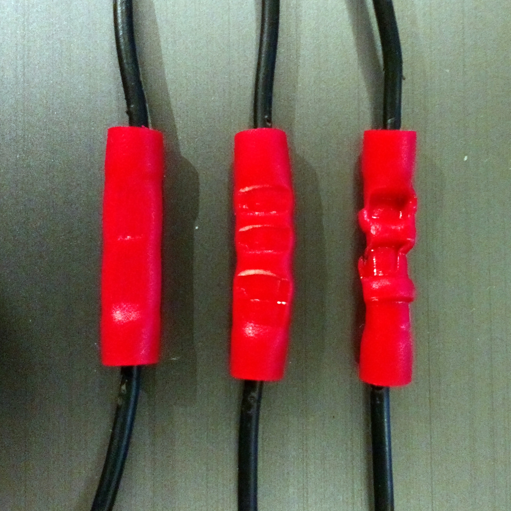
If I’m to evaluate some crimp tools, first I have to make some crimp connections to work with, so I robbed some wire from the mess of cables on an old ATX power supply, and took three red crimp cable splices appropriately sized for the wire. These are not special at all, being from a cheap retail multipack of crimp connectors.
The ratchet pliers made the most impression upon the red plastic, leaving it most visibly deformed in the shape of the dies. It is probable that an adjustment of the ratchet would change this, I’m simply using it as it came to me for now. Meanwhile the simple crimp pliers did their usual neat job, and the bench pliers merely flattened the connector into an oval.
To measure the effectiveness of a crimp connection, what do you need to know? In a lab you might cut through it with a precision saw and polish the exposed end for examination, or perhaps study it as a metallurgist would, with x-rays to see the effect upon the metal crystals. But on my bench I have neither of those things, and anyway my needs from a crimp connection are more down-to-earth. I need to know the following: Will it fall apart?, and Will it take the current I want to give it? So I need to examine its breaking strength, and its electrical resistance.
A Bit of Backyard Metrology
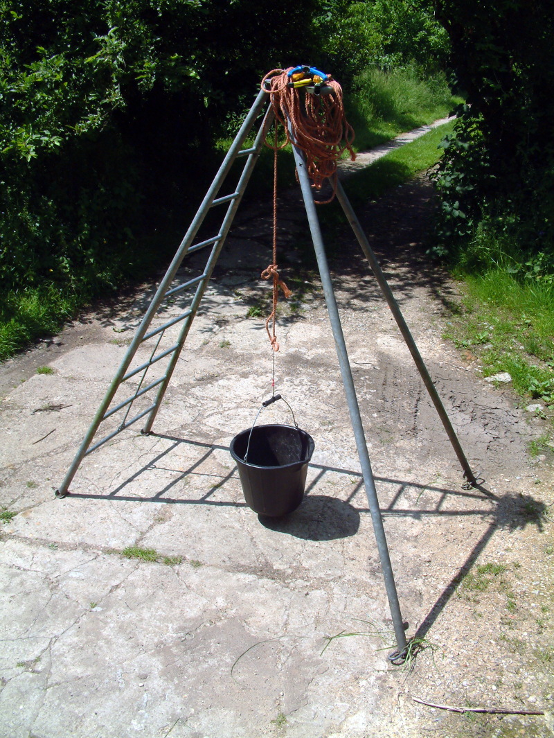
I lack a lab with a tensile strength evaluation rig, but I live on a farm and have ready access to a fruit picking ladder, and a bucket. The ladder is a roughly 6″/2m-ish tripod depending upon how you place its legs, so from it I suspended a bit of rope to which I tied my bucket via my wire with the crimp splice in it. By filling the bucket with water from a measuring jug until the splice parted I could gain a rough measure of its strength. There is a small weight from the plastic bucket, but since my resolution is one litre of water, or about 10 Newtons if you take mild liberties with the strength of English gravity, I’d say it’s within experimental error.
It’s probably one of the more unusual things I have done for Hackaday, sitting in the sunshine pouring water bit-by-bit into a bucket. A good tip should any of you feel the need to do this is to suspend the bucket only about an inch/25mm above the ground, because when the splice gives way there is a significant amount of potential energy in all that water which could split the bucket. As it was there was mild soaking of feet involved as each failure produced an impressive splash, but you have to take the rough with the smooth in the world of farmyard engineering.
The forces required to part the splices from each tool are collated in the table below:
| Tool | Litres of Water | Approximate Breakage Force (N) |
|---|---|---|
| Bench Pliers | 5 | 50 |
| Simple Crimp Pliers | 14 | 140 |
| Ratchet Crimp Pliers | 20 | 200 |
Straight away we can see that with a breakage force of only 50 Newtons, my bench pliers do not give a good quality result. This is hardly surprising, but worth recording. It’s also not a surprise that the ratchet pliers give a stronger result than the simple ones, this is probably a function of the better dies, and its lever action. It is a surprise how much better they are, but since a crimp connection’s purpose is electrical rather than physical it does not mean that the 140N strength of the simple crimp plier connection is inadequate.
Torturing Innocent Power Supplies in the Name of Measurement
So, we’ve established that in the field of tensile strength of a connection made by a given crimp tool, you get what you pay for. How about in our other field of evaluation then, the resistance of the connection? Here we immediately encounter a problem, and it lies in the tiny resistances involved. Crimp connectors are designed to offer as perfect a connection as possible, so their resistances are tiny. To measure a resistance in the milliOhms, you can hardly pick up your trusty multimeter and break out the probes. We live in a world of resistances in the kOhms, and normal instruments are not made for such tiny values.
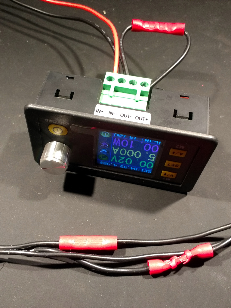
A few ideas were considered for how to deal with this problem, and in the end I settled upon one involving a current limited power supply. My multimeter is good at measuring tiny voltages, so if I apply the same constant current to all the various crimped connections I can read the voltage across them at a preset current and use Ohm’s Law to derive a resistance. Out came one of the ubiquitous Ruideng switching regulator modules set to its maximum 5A current value, and the voltage across all three crimp splices as well as a piece of wire of the same length was measured. The resulting values along with the calculated resistances are in the table below.
| Splice Under Test | Voltage at Regulator Terminals (mV) | Calculated Total Resistance (mOhms) | Crimp Splice Resistance (mOhms) |
|---|---|---|---|
| Straight Wire (no splice present) | 15.1 | 3.02 | 0 (No splice present) |
| Bench Pliers | 21 | 4.2 | 1.18 |
| Simple Crimp Pliers | 15.7 | 3.14 | 0.12 |
| Ratchet Crimp Pliers | 15.8 | 3.16 | 0.14 |
At first sight, it might seem that an unambiguous but unexpected tale of the crimp splice made with the simple crimp pliers being the one with the lowest resistance, but the reality has a significant contradiction. Even by switching to a voltage reading we are measuring at the lower limit of what it possible with an inexpensive multimeter, and relying on the current limiter on a cheap voltage regulator module to be a paragon of metrology virtue is a strategy that is never going to go well. So these readings all come with significant error bars, and thus are not as clear-cut as the numbers themselves might have us believe. What the figures do tell us is that there is a clear difference between the two purpose-built crimp tools and the bench pliers, but that as long as a crimp is appropriately compressed it makes little difference to the final resistance what tool makes it.
So after going further into the properties of a crimp connection than I have ever done, my conclusion is that while it’s nice to have a pair of fancy ratchet crimp pliers on my bench they really aren’t that much better than the simple crimp pliers as I’d have believed them to be. Meanwhile nobody would expect a pair of standard pliers to be much good at crimping, and I’ve amply proved that. What all this has shown about crimp connections is that for the tiny cost of a crimp splice you get a significantly strong and super-low-resistance connection if you use the correct tool, and given me a new respect for these ubiquitous connectors.


Next up, an article on the different type of crimp ends. Advantages, disadvantages.
“Mom? When can we get our swingset back?”
B^)
First. Throw out those awful pre insulated crimps.
There’s no way to get a good crimp through those nasty plastic things.
Get some of the double crimped type that also crimps on to the wire insulation.
And the correctly sized crimp tool with the W shaped press.
And then slip over insulation sleave or heat shrink.
.
Agreed, I could not have said it better !
I need a heat-shrink tube that shrinks about 8:1 because I inevitably forget to slide it on first.
You are not alone!
B^)
Now, if they could only make the threaded coupling sleeves for RF connectors in a heat-shrink version…
Heat shrink tube with a slit is what I need. Someone patent it and start selling it, please.
It’s called heat shrink tape, if you use it be sure to follow the instructions.
https://buyheatshrink.com/heatshrinktubing/heat-shrinkable-insulation-tape.php
They sell it for larger wires
It’s called Self-Fusing Silicone Tape. Look for ‘Mil Spec A-A-59163 / Mil-I-46852’ to get the good stuff.
Thank you guys, just what I needed!
This article, like many on Hackaday, provides a valuable service: it does not attempt to tell everyone the “best” solution and sneer at the lesser solutions, it supplies information about the tools and materials that readers will likely have lying around or find at the local hardware store.
Fair enought.
The point is, if you have nothing and need to invest in a crimper and crimps, don’t buy those, buy the proper ones ;-)
buy is maybe the wrong word. ‘found in a dumpster’ i believe is appropriate. spend money on parts, lol.
but i generally agree they are trash along with those non-ratcheted crimp pliers. if you buy them you might as well just burn your money it will produce the same results.
If you have nothing and feel the need to invest in crimps, consider investing in a soldering iron or soldering solution for the size of the wire that you wish to joint.
I’d bet that AMP would disagree with you — but what do they know?
^ This. I always use insulated crimps but try to buy decent Amp/Tyco ones and if done with decent ratchet crimpers (mine were only ~£30 but are decent quality and work very nicely) they are absolutely fine.
I’ve used crimpers costing £1000 and £1, undoubtedly one is better but if you know what a good crimp looks like you can make it work with the £1 ones, if you don’t even the £1000 ones won’t save you.
I prefer the TE PIDG insulated crimps. http://www.te.com/usa-en/products/terminals-splices/intersection/pidg-terminals-splices.html?tab=pgp-story The insulation is nylon or pvc, partially transparent, and the crimp itself has a metal ferrule to grab the insulation for a 2 point crimp. These are used in avionics applications, they are rather expensive, but they are one of the best crimp connectors I’ve come across. Too bad these aren’t available in similar quality from overseas sources.
I searched their site for “bullet” connectors commonly used in older cars/trucks, and what they displayed was “something else”!
(they could possibly be used for shooting! B^)
The ratchet mechanism is there to guarantee a controlled crimp cycle.
Right now my left wrist hurts from a skating accident.
I wouldn’t be able to crimp down with the same force as I was able to yesterday. Crimping with anything but ratcheting crimpers will guarantee only one thing… zero consistency. It works on the same principle as a click type torque wrench.
The crimpers , if it working correctly will not release till it reaches a set point.
I used and continue to use Sargent controlled duty cycle crimpers. Additionally the quality of terminal used has a strong bearing on the quality of the crimp.
The “cheesy” crimpers are meant to be squeezed until you hit the mechanical stop, if you do this you will get reasonably consistent results. If you are not getting consistent results then you are using the wrong tool.
That’s exactly it. You can still potentially generate a better crimp with a manual tool, but you can also easily produce a terrible one. A ratcheting tool will create good crimps consistently.
I’ve always believed that soldering was preferable to crimping, but without experimental evidence. The experiment to compare solder against crimping should probably include long-term stability in a salty or corrosive environment.
My decades-old understanding of measurement of low resistance is that the Kelvin Double Bridge is the best method.
The problem with soldering isn’t that it fails or is unduly susceptible to corrosive – for evidence, knob and tube wiring powers millions of homes, and it was all soldered and wrapped in rubber/asphalt tape.
The major problem with soldering is that it’s not idiot proof. Crimping isn’t either, but it’s harder to mess up; almost impossible with ratcheting-style crimpers.
When we got to soldering instruction in tech school the rule was/is that a connection should be both electrically and mechanically secure before solder is applied. One can choose to apply solder to a crimp. I used to until I began to note that stranded wire would break at the point where the solder stopped-traveling up the wire. This will forever be a YMMV thing.
I’ve seen this as well, but I don’t see this as YMMV. The problem with soldering stranded wire is that when you bend it close to the soldered end, the solder becomes the (very poor) strain relief. The strands at the outside of the curve take all of the strain, and they break.
It’s very dependent on your environment. In a robotics application, solder is inferior to crimping because it acts as a stress concentrator and can wick into the wiring. The length of wire which may have it’s flexibility compromised is both variable, and much longer than a crimp. In comparison, a good crimp connector is designed with stress relief features (See the wings that grab insulation on crimp pins), and can have a consistent strain relief added. Additionally, crimps have fewer issues with extreme temperatures (see 3D printer hotends, kilns, etc), as well as fewer issues with temperature cycling. However, solder, if you don’t need strain relief for motion, is much more compact, can be very low resistance, quite strong in tension (Lineman’s splice and similar), and easier to mass produce. Corrosion resistance is very dependent on your environment and methods. A good crimp is gas tight for the wire interface itself, as is a solder joint, meaning that if it’s a dry environment without a corrosive atmosphere, they’re probably equivalent. Both can be heatshrinked, including with the hotmelt adhesive lined tubing, meaning that both can be made watertight pretty easily (One might argue that crimps with heatshrink pre-applied are easier than remembering to get the heatshrink on the solder join).
So, if you’re not doing wiring runs that are likely to move, or need to be reterminated (IE, unscrew from terminal, then replace into a different terminal), solder is probably cheaper and if practiced, faster. If you need to be able to move the wiring, either while connected, or from connection point to connection point, crimping is better. And woe betide anyone who tins wire for a screw terminal.
soldering crimp joints is terrible practice, there is an enormous stress point where the wire emerges from the solder. If you have to solder to get a good connection then you should get a better crimping tool. What is the cost of the broken connection? Doing it right the first time is the cheapest.
It’s true that soldering a crimp (and some other types of ) joint does make it more likely that extreme vibration will cause the wire to work harden and break. This isn’t an issue in the #2 down to #000 wiring in my solar system, and just crimping that is an invitation to a fire with 1000 amp load and charge currents. You are not going to shake 2 tons of batteries (or for that matter, “wire” made of #10 strands bigger than your … in diameter) hard enough for joint fatigue to matter – if you do, something else is REALLY wrong.
That said, depending on a crimp to be a good strain relief is a cop out. If that kind of thing is a problem, you should be addressing it other ways *as well*. Most things don’t need to allow for large flex excursions except for servicing.
In the ’70’s I was an audio repairman. Supporting weight with wires (including the weight of the wire, but also any reasonably large component like an electrolytic) was right up there in the top 5 reasons things failed, right behind…using solder alone to hold headphone jacks (in this case it was half and half the solder joint going bad or the track pulling off the board or board breaking).
I also fixed a ton of bad cabling that failed just after the end of the nice strain relief – it was too stiff compared to the wire, though a lot more flexible than the ones I see in crimp connectors.
Moving the problem only moves it, it doesn’t solve it necessarily.
hmm that must be why the electricians soldered all the connections to our new 480V 200A transformer and load center… oh no wait they used screw lugs. There is nothing wrong with using mechanical connections for high power loads.
I fix musician’s gear – amplifiers and so on. These days the lead-free solder means that PC-mount jacks blow their solder joints first, but I have seen some PCB lifts before..
Crimps are pretty great at high currents you just need very expensive dies and tools:
https://uk.rs-online.com/web/p/crimp-tools/0445885/
A good crimp makes a gas tight connection so there is no issue with corrosion, at least not internally. Like others have said soldering creates a stress point where the solder wicks up the wire. And thats where they break.
For reference… the FAA forbids soldering a connection! Sometimes they do stuff just to be dicks, but others… there’s a reason! Vibration will eventually induce failure. And there’s no AAA at 30K ft. :)
This is a classic internet argument, the TL;DR is that soldering OR crimping are both equally valid and work excellently if done well.
NASA use both, aerospace uses both, industry uses both.
The reason a lot of stuff now gravitates towards crimps is that they are easier to do repeatably with low-skill or automation and don’t involve hot things and lead.
Nope, the issue is you don’t solder AND crimp, never ever.
You tested 1 example of each type? I’d have liked to see several of each type and the average of the results.
Could not agree more!
What? No current to failure test? How can you call this complete? I am sorely disappointed. I was expecting smoke, flame and explosive destruction! Surely you must have learned something from Mythbusters. If it’s worth doing it’s worth overdoing! Otherwise your message only gets out to those who are critically interested, and you have to bear the tedium of wading through annoying peer reviews without the affirming satisfaction of fanatical drivel from the media saturated, mouth breathing, TL,DR crowd!
B^)
This is great! I did a similar test, oh crap, over a decade ago: http://toolmonger.com/2007/02/16/test-to-destruction-crimp-terminals/
Since then I’ve learned a lot more about crimping and I should repeat the test, mo’ betta’.
Get to it, we’re waiting!
May want to go over your article and see about killing off those pharmacy spam links..
I never noticed any of what you indicated, perhaps you have problem on your end?
Hackaday journal of what you don’t know!
I see in this article:
1) Introduction
2) Experimental methods
3) Results
Absolutely nothing wrong with this as a scientific paper detailing citizen science. It’s too mundane for mainstream papers, but it’s something hackers should know about.
Repeat the experiments a couple of times each (say – 5 times each) to get a good average, so that you know your results are repeatable, and submit it to the Hackaday journal, please!
I agree with the exception of I would add a comment about “2b” which is “Experimental test methods”. I would prefer to see the crimping done the same way that most people do at home or in a makerspace, but then test those crimps with proper equipment.
The biggest factor in a successful crimp isn’t the tool, but the terminal. Cheap thin non-welded seam terminals will fail regardless of how good the tool used because they simply lack the fortitude to retain the wire. On the other hand, welded seam terminals can work successfully even with mediocre crimping tools (although a quality tool does result in a superior joint). But quality terminals aren’t cheap. It’s a classic example of “Buy the best and cry once”.
There’s a forth type of crimp tool that one should consider. It has a pin or ridge on one jaw that bends the “O” shape of a terminal into a “C” shape. This seems to work a little better on cheap terminals than the other tool do.
I use ratcheting crimpers from Anchor with their terminals – the terminals have a two size interior -the small part for the wire and the larger section grabs the insulation on the wire for strain relief
The crimps are also part mechanical as they want to turn the stranded wire into a solid block to keep air out. In the aerospace industry you have to use the ratchet crimpers and they are checked on a regular basis for the pressure and such – got educated many years back by an electrician that used to to aircraft wiring – and very exacting standards – due in part to reduce any chance of bad effects from vibration on the connector
What you call a plain pliers, I call a Lineman’s Pliers, what I call a plain pliers, is a slip-joint pliers…
And what I call 81’s you call, um…
Very nice article.
My rule for testing crimps: the wire should break before it pulls out of the crimp.
Googling will bring up all kinds of NASA and industry papers on crimp reliability
As has been stated above for different reasons, there’s much more to test! One of the real problems with the hand crimper is that it’s easy to get an imbalanced crimp. TE put out a good video on what goes into good crimps. At 4:09 in the video, you see cross section images of various good and bad crimps–and you see one of the real failings of the hand crimper. If you have imbalanced pressure applied to the crimp, you can end up with spaces inside the terminal-wire connection. Crimping, then strength testing turns out to not be enough! At the moment of the crimp, it holds strong–after all, there was pressure applied there to the right level (just not in the right places necessarily). But what happens after time passes–when everything has relaxed? The wire has been bent and shifted? The presence of those spaces allow the wire strands to shift position, removing the pressure that was there when it was formed. When I used a hand crimper, I found that even when I checked the crimp to be sure it held, after some time the terminal would pop off with no effort at all.
TL;DR: this test does suggest the ratchet style crimper may be overkill for home use, but as in most scientific studies, there’s still more to the story! More testing is needed. =)
Good test and article, thank you. Just add the same test for soldered wire if possible. Next article?
I’d like to see corrosion resistance. Maybe a controlled acid bath for each and then test strength and resistance.
I wouldn’t be too sure about accepting the results using the cheapie crimper as being roughly equivalent to those obtained with the more expensive tool. One of the goals of crimping is to obtain a ‘gas tight’ bond between the metals, as this renders the connection less prone to oxidation and makes it more reliable over the long term, especially in more adverse environments. I suspect the ‘good’ crimper accomplishes this much better than the one that comes with some cheap terminals included. Also, thermal cycling of connections causes expansion and contraction. Over time, the crimp can loosen, increasing the resistance. In turn, the temperature swing increases, the joint becomes looser the resistance increases again, and so on, until the connection fails. Again, the tighter crimp provided by the more expensive tool mitigates against this.
There’s a very good reason the pros use the more expensive tools, and are careful about properly matching the dies to the parts they’re using. Doing so results in more reliable, safer connections.
Marine How-To covered this topic too, including the best kind of crimp terminals to use in a highly corrosive (salt water) environment. When boats catch fire it’s a little harder to call the fire department, so taking care of the crimps properly is a good idea.
https://marinehowto.com/marine-wire-termination/
Well, at least with a boat fire, there’s no shortage of water……
I love the idea of ratchet crimpers, and the relative prices suggest that simple crimp pliers aren’t worth it, but HOW ON EARTH IS ANYONE SUPPOSED TO USE DIES THAT CRIMP WIRE AND INSULATION AT THE SAME TIME?
Doing them in separate steps you can easily see if you have it lined up. Doing them at the same time is guessworkful and obnoxious.
If you use the right size wire, trim the wire correctly and otherwise do everything correctly, the one-shot crimpers are great. The wire gauges and strip lengths for your terminals should be documented. You just need to make sure you have the right pieces and are doing it correctly. I’ve seen trained technicians prepare hundreds of perfect crimps per hour with the one-shot crimpers.
[quote]
Even by switching to a voltage reading we are measuring at the lower limit of what it possible with an inexpensive multimeter, and relying … [/quote]
not anymore you don’t.
Aneng is setting new standards for cheap multimeters and te AN8009 has a resolution of 1uV, which is 2 digits more than usual.
As a hack you can use a DMM with temperature measurement.
A type K thermocouple has a tempco of 41uV/Celcius so that is around 4uV if it has a 0.1Celcius resolution, which probably makes this the most sensitive range of many multimeters. You wil not get “real” values, but for comparative measurements such as here that does not matter.
I used to use up 100’s of crimps a week when I was doing electrics on trucks and trailers, I much preferred the type that was insulated with heat shrinking material with internal glue.
100% water tight and didn’t need any other shield for the enviroment (although I often bundeled them with heatshrink anyway)
It could be hanging under a trailer driving on salted roads for years without failure.
All crimped with an (expensive) ratcheting tool with correct colour codeing :D
no one commenting on the position of the crimp on the terminal’s barrel?
As I understand, part of the process with these types of crimps is having the crimp halfway along tthe barrel. the point being that where the wire exists the crimp, there’s a gradual transition from tight/crimped to loose wire. strain-relief, sure, but also assuring the wire isn’t *cut* by the barrel’s edge. This is important on the wire-side for obvious reasons, but *also* where the end of the wire exits the barrel (or at least, the crimp), to help prevent pull-through. A straight-out pull test doesn’t tell as much if the wire’s nicked. in fact, it may appear stronger at first, until those nicked strands break free over time.
Major argument against straight-up pliers… better with needlenose, if the same force could be applied. Also, of course, the insulation-crimping inherent to most ratchetting crimpers is probably a good thing.
I *dare* anyone to look at that ladder/bucket combo and post “not a hack” !
Only award for winning is a…paycheck.
Getting one good crimp with an inadequate tool is very well possible. Getting reliable crimps with a sufficiently low failure rate (maybe 1%, 0.1% or even less, depending on the application) is another thing. The ratchet will probably have by far better reproducibility than the other options since the crimping force is fixed by the mechanism and not depending on the (variable) hand force used by the operator. Would be interesting to see the results of a proper test with e.g. 10 or 20 crimps with each tool and a comparison of the worst and average resistance for each tool.
The wire strands need to be twisted as opposed to straight. Once the crimp is made the wire will splay out to fill the gaps. The more the crimp I.D. is full before crimping the stronger the bond will be, both physically and electrically. If the crimp is not as full of wire as possible the bond will suffer. If necessary fold the wire until the crimp is full.
Vic
Wires should not be twisted any more than the natural twist of the wire.
In a pinch I have folded over wires when I did not have any crimps of the correct size but it is not a recommended practice.
Hey macona
Wires do not have a “natural twist” from my experience: The manufacturer imparts any twist or braiding they desire to provide the needed flexibility for the application.
If the correct crimp is not available then you must improvise, recommended or not.
@macona is surely referring to the “lay” of twisted stranded wire. Many crimp and wire preparation standards recommend against twisting the strands beyond the natural (manufactured) lay pitch. I don’t know the reasoning behind this recommendation, but I imagine that twisting the wire end tighter can create a kink in each strand where it exits the insulation, increasing likelihood of fatigue and failure.
https://fiskalloy.com/products/conductor-facts/lay-direction-and-length/
Good point. I have seen the strands straighten just from pulling the cut insulation off. It is hard to tell the “lay” of the twist if that happens. I got into the habit of twisting the insulation as I pulled it off, so there goes the “lay” of the wire right out the window.
Vic
Thats the natural twist I am referring to, most stranded wire has some amount of twist to it which keeps it bundled together before the insulation is overmolded. Some people twist the wires more after they strip them which is not necessary and can cause issues.
No, do not overtwist and never fold the wire. If it doesnt fill properly you are using the wrong terminal. Read NASA’s wiring standards please. They are well thought out and tested and used for all kind of mission critical applications.
NASA has a nice doc on crimping and harnesses:
https://nepp.nasa.gov/files/27631/NSTD87394A.pdf
These bench pliers of which you speak,…..
Did you just squash them flat (like the picture suggests) or did you use the cutting edges to gently dent/compress the splice barrel?????
I have used the cutting edge to compress the crimp. Just pay attention and redo the splice later if possible.
Actually Hackaday had a great article on the physics behind crimping a year ago: https://hackaday.com/2017/02/09/good-in-a-pinch-the-physics-of-crimped-connections/
If you crimp too hard, you will weaken the stands and the connection will break. As an engineer who have worked more than 15 years with connectors and cabling, I can tell a lot of horror stories about bad crimps. There’s a huge difference between a few crimps in a DIY project and producing thousands of products reliably. For the latter, have a look at this article: https://www.edn.com/design/components-and-packaging/4421838/Bad-crimp–bad-news
That 2017 article is awesome. One of the comments mentioned sweat and oils from your fingers contaminating the joint. I have contaminated a lot of splices. WOW.
Two of the three tools are not for that standard, do not use the wrong tools för crimping. The title maid me think this was an interesting artice about different crimping systems, but soon found it was about using the wrong tools for a specificerat system. Never use the wrong tools if you can avoid it.
Ratcheting crimpers are useful for repeatability and ensuring a complete crimp. Besides the obvious benefit of that, it’s a blessing when you have to crimp terminals on wires that are not sitting right in front of you on a bench, but instead tucked up in something that’s a pain to get to. The better terminal crimpers also tend to have a wire stop that prevents you from sticking the wire in too far – again, something that’s really appreciated when you can barely see what you’re doing. If you use terminals quite a bit, then do yourself a favor and buy a decent ratcheting set – you’ll be glad you did.
Judging from the pictures it looks like the ratcheting crimpers the author has are intended for uninsulated crimps. In the pics they look a little “over-crimped” which might be caused by the plastic insulation
I wouldn’t be too sure about accepting the results using the cheapie crimper as being roughly equivalent to those obtained with the more expensive tool. One of the goals of crimping is to obtain a gas-tight bond between the metals, as this renders the connection less prone to oxidation and makes it more reliable over the long term, especially in more adverse environments. I suspect the ‘good’ crimper accomplishes this much better than the one that comes with some cheap terminals included. Also, thermal cycling of connections causes expansion and contraction. Over time, the crimp can loosen, increasing the resistance. In turn, the temperature swing increases, the joint becomes looser, the resistance increases again, and so on, until the connection fails. Again, the tighter crimp provided by the more expensive tool mitigates against this.
There’s a very good reason the pros use the more expensive tools, and are careful about properly matching the dies to the parts they’re using. Doing so results in more reliable, safer connections.
My father taught me “A good electrical connection begins with a good mechanical connection.” An oversimplification with some exceptions, but nonetheless a good rule of thumb!
Hi,
I have all 3 of the tested “crimpers” (and others besides), and I’m also ABYC certified in boat electrics. Some notes.
ABYC has a spec for how much pull a proper crimp can withstand, but I don’t have it handy.
Don’t use regular pliers or cutters to crimp, except in an emergency, and replace or re-crimp it properly later.
The non-ratchet crimpers – better than ordinary pliers, but you must know beforehand how much pressure to apply to make a good crimp. Ratchet (“controlled-cycle”) crimpers give the most repeatably good results, even in beginners’ hands
I know (and have) those cheapie ratchet crimpers used here. The colour dots are NOT wrong; the red and blue holes are correct; the one they mark as yellow is actually one size smaller than red. Those particular crimpers will not do the larger conventional yellow lugs.
I’ve found variance in both lugs and ratcheting crimpers, so for maximum quality, you need to select and stick with one brand of lugs, then select and set up your crimper for them. There’s usually an adjusting “spur” on the tool which sets the “closed” end of the cycle. A mediocre ratcheting crimper, properly set up and tested, is better than a top-end crimper used on lugs it wasn’t set up for.
Since Unior 514 or gedore 8133 and similar there is no excuse for “emergency use of cutters for crimping”. Those tools are cheap and small enough to have them for any emergency use. Leaving crimping for later improve or using cutters for crimping purpose is asking for more emergency situations.
So next time I’m stranded in the middle of the ocean, and I find the proper crimp tool rusted solid, or dropped overboard, I should NOT use a pair of pliers to fix my life-critical error (like sump pump, or starter, or the power line to the sound system and TV to entertain people) and be underway? Good to know. Where do I send the bill for my life insurance payment? ;)
My point is that in my career on offshore vessel electrician 90% of bad practices was (and still is!) lazyness and “silly money saving”. Examples:
– I will do it like this now and correct later. And later happens when bad practice becomes a problem.
– Workshop is so far.
– Tool bag is so heavy – I can do everything with my leatherman multitool.
– I can’t find crimper – for sure it’s lost.
– I got this 2$ pliers that do the job of this 10$ crimper.
Your example is very extreme. And of course if you don’t have what you need you work with what you have. But what would you do if you dorped also your cutters? Is new solution worse or just take more effort? And why you don’t use any type of harness when working overboard or at high? Why don’t you do some housekeeping – none of my tools have ever got so rusted. You are heading to the middle of the ocean and you give no care to your resources knowing that you have no backup? I know extreme situations happen – but I find a bad practice much more often than I meet extreme situations.
I would love to see your “everyday carry” tool kit, plus whatever survival stuff you must always have with you.
Vic
After crimping, wrap on a few layers of Self-Fusing Silicone Tape. (Look for ‘Mil Spec A-A-59163 / Mil-I-46852’ to get the good stuff.)
Time to find a hobby store for two bottles of paint, blue and yellow. Are both sides of the lower jaw painted wrong? Extra points to anyone that can properly name the two crimping faces (which is eluding my carbon-based wayback).