I had a friend who was an electronics assembly tech for a big defense contractor. He was a production floor guy who had a chip on his shoulder for the engineers with their fancy book-learnin’ who couldn’t figure out the simplest problems. He claimed that one assembly wasn’t passing QC and a bunch of the guys in ties couldn’t figure it out. He sidled up to assess the situation and delivered his two-word diagnosis: “Bad crimp.” The dodgy connector was re-worked and the assembly passed, much to the chagrin of the guys in the short-sleeved shirts.
Aside from the object lesson in experience sometimes trumping education, I always wondered about that “bad crimp” proclamation. What could go wrong with a crimp to so subtly futz with a circuit that engineers were baffled? How is it that we can rely on such a simple technology to wire up so much of the modern world? What exactly is going on inside a crimped connection anyway?
Solderless Makes Sense
We tend to think of soldered joints as the king of electrical connections. Something about the act of heating up a joint and flowing molten solder into it lends a feeling of permanence and quality to the finished product. And soldering was basically the only show in town for the early days of the commercial electronics industry.
But soldered joints have their problems, both electromechanically and in terms of production – after all, an assembly worker can only sling solder around so fast. In the early 1950s, AMP Corporation came out with the first crimp connections for production use, the F-Crimp or open-barrel design. Using this crimping design, AMP sold a wide range of connectors that could be rapidly and repeatably applied to conductors, and that lent themselves to automated fabrication methods in a way that soldering would never be able to achieve.
Squeeze Play
Crimping takes advantage of the properties of metals to achieve electrically and mechanically sound connections. Metals used in crimp connectors, like copper, brass, aluminum, or bronze, are both ductile and malleable. A metal’s ductility is the degree to which it can deform under tension, while malleability is a measure of how metal deforms under compression. Crimping involves applying significant compressive forces onto the crimp connector and the wire, so the malleability of each element is an important factor in crimp quality. But ductility plays a role too as both connector and wire undergo significant stretching during the crimping process.
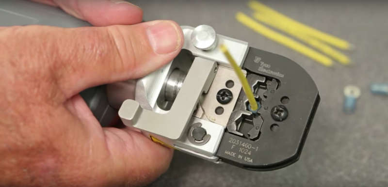
Crimp tooling is a critical part of a quality crimp. The business end of any crimping tool is the die set. This is generally a tool-steel anvil and hammer, the specific configuration of which is determined by the connector type.
For AMP-style F-crimps, the U-shaped connector is placed on the anvil with its legs up. A properly stripped wire is placed between the legs, and the hammer moves down onto the anvil. The hammer guides the legs of the connector over the strands of wire, eventually folding them back down into the gathered bundle of strands.
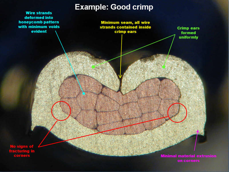
As more pressure is applied to the connection, metal in the wire strands begins to stretch and flow. This loosens and drives off any surface oxides that might have increased the resistance of the connection. With more pressure comes more deformation of the wire bundle until the formerly round cross-section of each strand is gone, replaced by a collection of strands with flattened sides snugged up next to each other in a honeycomb pattern. The result is cold-welded, gas-tight junctions between the strands and the crimp connector.
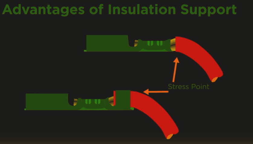
Most crimping tooling also takes care of strain relief by lightly crimping a second set of legs onto the plastic insulation of the wire. Care is generally taken not to pierce or otherwise mar the insulation; usually these strain relief crimps just wrap the insulation firmly and direct the force of bending into the insulation and away from the wire’s conductors. A third set of legs may also be formed into a circle by the tooling to permit the finished termination to be inserted into a plastic body.
A critical aspect of a crimp connection is the ability to inspect it and be sure that everything went according to plan. Cross-sectional photomicrographs of crimps are the gold-standard for inspection, but are destructive to the product. Luckily, one critical parameter can reveal everything about the crimp process and be measured non-destructively – the crimp height. This can be measured with a micrometer and reflects how much pressure was applied and whether the wire strands were properly compressed.
A properly executed crimp connection is electrically reliable and mechanically strong, and knowing what’s happening inside that tool is the first step in achieving consistent results. For a more in-depth hands-on tutorial on crimping, see our guide to proper crimping procedures.
[Source for banner images: TE Connectivity]


Thanks! I never knew most of those things about the lowly crimp connector.
In re-wiring my 1942 truck, I was planning on soldering a lot of the connections, it’s comforting to know a better connection is possible through crimping.
For a follow up article, consider sonic welding for wires.
Soldered connections with standed wire tend to break at the point where the solder stopped wicking into the conductor strands. The solder containing part it fairly rigid, and the sharp transition leads to a stress riser. The heat and change in material property due to flux and solvation on the solder into the conductor can make it worse.
Good point. I like to add one or two layers of heat shrink tubing over the cable before soldering. That way the mantle does not retract and peel away and the transition point is reinforced form the outside. This treatment has proven effective in assemblies that were subjected to continuous vibration.
Soldering may still be important if your dealing with a radio noisy environment though. My father taught me when you crimp a good connection to put just a dab of solder over only the exposed portion of wire. His demonstration showed a clear separation of wire soldered down, bare wire and then the crimp. As he put it the crimp is primarily for structure support, the solder for electrical support don’t mix the two.
Your father was wrong.
What an informative and useful reply. I’m fighting the release rage, really, I am.
Could you please explain why his father was wrong?
Seriously, if you can’t reply in a constructive manner where you provide evidence for your claim, why even bother to reply at all?
Care to explain why his father was wrong?
A correctly done crimp will be stronger than a solder joint. Adding solder just makes it more brittle, which is not good in an automotive application subject to vibration.
If you say the sky is green, and we know that you are wrong, should anyone bother teling you tha you are wrong and why ?
Andrea: The article explains why his father was wrong. If you’re looking for an explanation then read the article.
You think that Jerry owes an explanation, yet you don’t question the opinion of a person that contradicts the article and commercial and NASA standards simply because his father told him. Is that any better than a statement with no explanation? That reply is less than “informative and useful” as it presents incorrect information.
What his father may have intended is that if you have wire with sharp ends (like when cut) on a HV connection, you may get something like a corona discharge from the very tips of the cuts. This can create electrical noise. In that case, a rounded ball of solder JUST on the TIP of the wire may help. Sort of like the little balls on the ends of antennas. But that doesn’t jive with the second half of the claim as that solder does not provide any electrical nor mechanical support. Maybe something was lost in translation or memories.
Just to clarify, soldering a crimp defeats the purpose of the crimp. It heats up the different metals in the cable which cause mechanical expansion/contraction, which can reduce the quality of the crimp. The solder doesn’t really add anything either.
Basically, if your experience is that soldering a crimped connection makes it last longer, it was improperly crimped in the first place. That being said, DIY crimps vs solder are a different story, if you don’t have the right tools at home, you are most likely better off soldering
Here is a bunch more.
https://standards.nasa.gov/standard/nasa/nasa-std-87394
NASA-STD-8739.4
WORKMANSHIP STANDARD FOR CRIMPING, INTERCONNECTING CABLES, HARNESSES, AND WIRING (Revision A 2016-06-30)
I also use this resource:
http://www.molex.com/pdm_docs/ats/TM-638000029.pdf
I have to disagree with this article. The first solder solderless connectors were invented in 1934 by Thomas & Betts Corporation called Sta-Kon.
I have been in Electrical and electronics for about 40 years now, and I can confirm that Thomas and Betts connectors were most probably the first. Very good for wiring things that tended to get hot….
Uncas A Whiticar in Harrisburg, Pennsylvania was the first. He set up the Whiticar corporation which became Aircraft Marine Products….AMP. His crimps revolutionised the electrical terminations in aircraft wiring , sped up production and facilitated military aircraft production . AMP started in a small workshop above a shop and grew into the global leader it is today,albeit not under Tyco Electronics or TE Connectivity as it’s currently known. AMP purchased Thomas and Betts in the 90’s. AMP was truley a global company that thought and acted locally. A fantastic company
Never ever use soldered connections in cars since the tin will crumble and connection will most often fail within a year. Production connectors are crimped for multiple reasons, reliability being most important. Cable splices are made with ultrasonic welding for reliability. Soldering is only to be used for PCB mounted components and soldered connections should at least be be encapsulated with epoxy.
The thing that sucks about crimp connections is that you need a different $150 crimper for every different terminal.
That’s true. I’ve been working with the wrong tool for years, my coworkers told me just to use this one crimper for everything and select one awg smaller than the actual wire and terminal. What a horror!
Thankfully now we ordered a new tool and proper terminals, no more messing around! No never again.
$150 is actually pretty low for a lot of the official OEM crimp tools. I’ve noticed Japanese connectors tend to have extremely expensive crimpers. Think $1300 or more depending on the connector family.
For my home projects I tend to use the cheap, crappy crimpers that I happen to already own even though they aren’t the right tool. I smash down the crimp as hard as I can, squish a bit more with needle nose, and carefully apply a little solder for good measure. At work I make my employer buy the correct tool and do it the proper way.
Soldering a crimped connector makes it weaker and more likely to break..
That said I have done it to repair a bad crimp in my chinese one hung low brand hot air station. I didn’t have any the right size so I just added a bit of solder to the crimp so there’d be a good electrical connection (even if it’s a terrible mechanical one) since the station itself doesn’t move much.
I agree it should be avoided when possible, but it can work in a pinch. Especially if care is taken so the solder flows the least amount down into the wire as possible and heat-shrink tubing is used (when possible) to strengthen the crimp and create a little strain relief.
Soldering a crimped connection is a bad idea.
Heating the crimped connection to solder temperatures causes thermal expansion that destroys the quality of the crimped connection, while the space created upon cool down isn’t available during solder flow.
Do one or the other, not a quarter-assed combination of both.
I can’t believe that a small seal at the brush in the front of a crimp destroys the good properties of the crimp. Why? I have seen crimps used to carry 700Arms and getting really hot. So if heat was a problem, the high current crimp must have suffered. But it didn’t.
Also, thermal conductance is high so the temperature difference between crimp and copper is quite low. Being gastight should also stop the solder from flowing too deep inside the wire (which I admit _would_ deteriorate the crimp).
So yes, I always crimp with the right tool _and_ seal the brush at the front to stop liquids from getting inside. So far it always worked well, but I love to stand corrected here if this actually is bad. And please also give a reason, which helps me to understand.
This, of course, is only for crimping, _then_ soldering.
Nope, just use a vise-grip!
I actually learned a lot from this article. Will probably invest in a few new tools.
I once crimped 4-gauge wire (where the conductor is about as thick as a pencil, it was being used as the alternator output wire for a 4×4 with an upgraded alternator that sees heavy offroad use) using a hammer and a concrete curb. It’s been working well for over 2 years so far!
LOL, made a ‘crimp’ using a hose clamp; it did not last very long.
All of my welder connections are made with 2 gauge wire smooshed in a piece of copper pipe with a bottle jack, then a hole drilled through.
Good luck doing a JST connector with vice grips!
That’s what needle nose pliers are for!
I’ve used the brake-fitting vice-grips in a pinch. ;-)
You can even dial in the force for some repeatability.
Why is there no standard crimp die form factor like we have with hex screwdriver bits? Or is there?
There is, for prosumer-grade stuff. The standard Eclipse/Paladin frames will fit most dies of a similar shape. When you get into weird industrial stuff there may not be dies available in that shape, but that’s somewhat rare for hackers to encounter.
xkcd knows the answer about standards
https://xkcd.com/927/
In general this is true. But I found some tools on Aliexpress for around 15$ and extra matching die sets for different types of contacts (open barrel, tube, insulated, wire sleeves, etc) for something like 3-5$ and they are quite good. They have a ratchet mechanism and make stable connection. I think they require a little more operating force than the expensive ones, but form low quantity home use this is completely OK for me. Much better than the crappy single sheet metal “universal crimping pliers” which are sold in cheap kits with assorted insulated terminals (which bend and make “connections” which can often pulled out by hand).
Links?
No, they keep falling apart.
Nah. You can get a LOT of mileage out of four crimpers that cover a very wide range of applications:
For the very small open-barrel stuff, get an Engineer PA-09: https://smile.amazon.com/Engineer-PA-09-Micro-Connector-Crimpers/dp/B002AVVO7K
For the mid-range open-barrel stuff, get a Ballenger micro: https://www.bmotorsports.com/shop/product_info.php/cPath/111_112_170/products_id/364?
(For large open-barrel, their “wide range” model is great, but I rarely encounter that stuff.)
Closed-barrel (mostly insulated) terminals will be well-served by any of the red/blue/yellow cheapies out there, though I’m honestly quite fond of the indent style, like the WT-11 or this: https://smile.amazon.com/Gardner-Bender-GS-388-Crimping-Electrical/dp/B00079LN1Y/
And for the large stuff, which is mostly closed-barrel, a cheap hydraulic hex set will serve you for years: http://www.ebay.com/itm/281746224039
this is a very helpful post. Thanks.
For the sake of everyone that has had to debug a bad crimp don’t do this if you’re actually shipping product. There are lots of places that will do wire assemblies for cheap. It will work for hobby and prototype stuff though. Just do a pull test on every crimp – twice.
When I was in the Air Force, we used similar tools to crimp RF connectors.
http://www.dmctools.com/Products/crimp_tools.html
https://www.astrotool.com/Products/power-assisted-crimp-tools-pneumatic
These are used for closed barrel contacts, such as made by Mil-Max. In some cases we have taken the tool apart and reassembled into a table, and used a vibratory bowl feeder to supply the contacts, under PLC control. This way we can semi-automate the production.
The second problem is that if you buy the cheap “universal” ebay crimper (you know the one, blue handle) it doesn’t crimp for shit. I have two crimpers, they look identical, the cheap ebay one is garbage, and the real one works like a charm.
The one I used in the video, below, was a $15 eBay tool. With the blue handle. It seems good. I don’t know how it could be better, but maybe it could, and now I’m curious!! Can you watch the video and respond if anything is obviously lacking about this tool?
It does take a while to make venous at first but that was due to those little parts, and my eyesight ain’t what it used to be.
I watched a few mins of the video. The ebay ones I have are different. (usually sold as “Molex Style” (blue handle) or “AMP style” (red handle) open barrel crimper.) If you don’t buy the right pins and expensive crimper you need for those pins then it’ll be a huge pain the the rear like you know. If you don’t want to spend $200 on a single-tasker (no matter how satisfying it is to use) then buy every universal crimper you can find and keep testing until you find the right tool to crimp with.
I have a few of the single wide (mentioned above, only crimps one set of ears at a time so every pin you crimp twice) and one set of pins I use I have to use two different crimpers to get it right, or chop some length off the ears, or pre-crimp them with one size larger then recrimp them the right size, or… or… or… you get the idea. The harbor freight (or home depot, I forget) red handled dual wide was actually pretty decent at crimping.
When we use the “f-crimp” in a production setting, we typically use an applicator in a AQMP K- or G-press
http://www.te.com/usa-en/products/application-tooling/wire-processing-equipment/bench-top-crimping-terminators/gii-terminating-machine.html
Of course, the contacts come in strip-and-reel.
Connectors are the bane of reliability, and have been for a long, long time. Read “The Soul of a New Machine” for a 1970’s vintage story about bad connectors.
Yep – the weak link in any number of technologies, not just electrical ones. Ask anyone in a field that features cable swaging.
Right – because everyone knows how to set a compression fitting without ever having been shown how.
Tracy Kidder’s one of my favorite artists. Actually, though I’m an EE, I really preferred “House”. Kidder really has a way of vividly painting characters, warts and all. You can’t help hating and falling in love with the people in his books.
Don’t forget about wire wrap. Works well with “squared” off connections like you may find with IC header pins. Not as well with rounded connections as on resistors and so forth. But then it is easy to just add a dab of solder to keep the wire wrap from falling off if its an issue.
I love learning this kind of stuff! I have wondered about this.
I use to work for Honeywell not too long ago. Can’t tell you how many times I failed assemblies for bad crimp joints. When done properly this is an excellent way to connect a wire. But a nightmare to diagnose when it is not done properly.
i try to use screw terminals as much as possible.
Screws can work lose under vibration or thermal cycling. So they are not the best way for every connection. A proper crimp connection is more reliable.
I have a 3-phase power plug in my show-and-tell box that shows what happens when a screw gets loose (I occasionally teach a basic electronics class)
I’ve noticed with a dab of blue thread-lock this has been one of the most reliable forms based on experience and reviews of these types of terminals.
That crimper in the picture is $703 plus $114 to $428 for the die set.
I crimped probably thousands of crimps in a past-life… I had no idea the wires deformed so much! That cross-section is pretty cool.
You should see what happens after you use the correct crimper on the Anderson PowerPole contacts. It squeezes them so much the crimp barrel actually gets longer.
People forget the material has to go somewhere.
Not necessarily. If you have a REALLY good crimper, you can start making miniature black holes at home (and artificial diamonds, but don’t tell anyone)
The photomicrographs show thick black lines around each strand and at the surface of the connector which seems to go against the idea that the materials flow together to make a gas tight joint. Or did the guy who prepared section specially treat it to show the boundaries?
Almost certainly treated with that blue stuff. And I assume that the cutting process separated the strands a bit from each other.
What I’ve seen done they cut the terminal and during that the process the strands get blurred (smeared?) together. Then they polish with different grits, finally acid etch the ‘blurs’ away.
Etched. Using acid etch on a homogeneous lump of metal* will show grain boundaries though those tend to be smaller… I’d still assume it to be gas tight however that is from reading, not experience.
(* except monocrystalline ones)
That’s why gold plated connectors can be, well, golden.
It’s malleable enough to fill tiny voids, like thermal paste in thermal applications.
Thanks for posting an appropriate video to go with the article rather than some random YouTube video from someone claiming to know crimps. Molex also has a “Crimp Handbook” that I have used as training material for years. (Google Molex 63800-0029 and download the PDF)
My only issue with this video is the statement made about “cut or nicked strands are not acceptable”. That varies upon the specification for the cable assembly. For example, per IPC-620 SS3 has a table for Allowable Strand Damage. So, while I agree that your process should be such that strand damage is 0%, there are variables that can impede that, yet not be a factor in finished assembly performance.
I deal with crimps on a daily basis and have spent years specifying crimp tooling, training, and design solutions. My team currently manages 4 crimping presses (2 Molex, 1 AMP/TE, and 1 Panduit), about 20 applicators for those presses, and about 140 crimp tools. As to the others that mentioned cost, yes, lots of money in tooling in that area of the production floor, and JST is usually the worst. Although, I do have one Hirose crimper that was $2600.
I do the electrical repair of a number of older and modern Toshiba milling machines, they use a lot of the Hirose, JST series, and Amphenol connectors.. it just has to be the expensive ones ;)
I can’t believe it hasn’t been mentioned before, but Viva Anderson Power Pole connectors! I’ve used so many that I’m going to need a new crimp tool soon.
vice grips for small terminals
v-block, dull centre punch and a 4lb lump hammer for bigger ones.
I jest, but proper proper crimp tooling is just too expensive for the home gamer, while frowned upon I prefer to crimp with a cheap tool, flow a little solder, then heatshrink or tie the cable in such a manor to allow mechanical relief if required.
In automotive wiring (where i do most my work :( ) biggest issue to wiring is moisture and second vibration. crimped connectors are not always immune to water ingress and galvanic corrotion, its interesting to note honda (among others but hoda is a good example as electrically there track record for reliability is amasing) crimp and solder all there large gauge connectors which are not waterproofed. the solder essentially provides the waterproofing.
what im getting at is while technically a crimp alone should be grreat, for us mere mortals with normal tooling budgets a little solder goes a long way to help a reliable connection.
In the automotive setting, do you ever use oily/waxy contact coatings (like Grote’s Ultra-Seal, Boesheild T-9, etc) to protect connections?
I occasionally do marine work. We use tinned stranded wire with “marine-grade” jackets, crimp-ons with heat-shrink insulation, and for the best protection we will try to get just a little solder into the open end of the crimp.
On my own boat, I’m trying the terminal strips with the added plates that clamp down on the stripped wire. So far, so good (4 years) Some guys use the Euro style whitish terminal strips that screw down onto bare wire.
A proper crimp CAN be done with cheap tools (yes, even needle-nose pliers) if you know what you’re doing, and do it right every time. The expensive tools are necessary only if you need to guarantee that every joint is done correctly — i.e. if you’re a company or a professional.
Also, many people are saying the problem with a soldered joint is mechanical, that it causes stress risers where the wire emerges from the solder. That’s true, but it’s also true that a properly crimped connection has lower resistance than a soldered one! Copper is a much better conductor than tin or lead, the components of common electrical solder, and the cold-welded joint described in this article provides for lower contact resistance.
Harbor-Freight has a ~$30 ratchet crimper for the the red, blue, and yellow terminals from the hardware store. I got one and it’s been a reliable work-horse for me.
A decent crimper will have controlled-cycle – the ratchet-y think that makes you squeeze the tool far enough to get to the required pressure before opening up again. This ensures that every crimp is sufficiently crimped. You can get controlled-cycle crimpers for ~ $25 and up. The biggest determinant of the crimp quality is the tool’s setting; they must be set up for the crimp lugs you intend to use. You can have the most expensive brand X crimper, but if you use brand Y lugs and they are slightly different, your crimps could be crap.
The biggest problem with a solder joint is that if it gets hot enough (eg excessive current, loose screw), you no longer have a mechanical connection and the wire can come out. For that reason many standards bodies do not consider just solder as an acceptable connection method for lugs on power conductors. They must be crimped; you can solder afterwards if you insist.
I would fear that the large heat cycle of the soldering could weaken the crimp. Except in an emergency without a useful crimping tool I would prefer a decent crimp connection. Of course, if I had to resort to needle nose pliers or a vice grip for crimping it could be useful to additionally solder.
In my experience, the soldering doesn’t weaken or harm the crimp, though you’re likely to melt the plastic sleeve.
But about the only thing soldering might do is block water intrusion from the end; it doesn’t make the conductivity of a GOOD crimp any better. You can use a soldering gun to quickly tin the wire end in the open end of the barrel, to thwart water. If you’re fast and the tip is hot, the plastic sleeve stays put.
HA wait till you get to the large wires.
Like 4 ot. ( 0000 )
To small.
OK lets goto 500 mcm
Wait I can go more 1000 mcm.
Ok last one and I don’t know the size I for got.
500,000 volts 5,000 amps. I think on the amperage.
And here is were you can not crimp.
OPG. Nanticoke in southern Ontario.
Coal firing electrical plant. 4 lines of 500,000 volts and 230,000 Volt lines.
Those were the largest so called wires I’ve ever worked on in my life.
I’ve worked on some cool stuff threw the years.
And Why is it the germans and the japanese think wire is small and easy to bend and crimp.
They give us no room to work in the equipment with. I really don’t know how it ever gets approved for use.
Probably rambling on. But OH WELL.
https://www.youtube.com/watch?v=q3lku3IcT9o
Love it.
That why child labor is so essential to electronics manufacturing lol
Hold on, so how did you make and secure connections? Did you weld those ” wires” in, was it some kind of bolt on vice system, or something else?
They use massive hydraulic crimpers.
I’ve never worked on anything larger than 4/0(4 ot) as he calls it. And in normal electrical panels its a Allen Lug assembly you put the wire in and torque down. Works wonders. My uncle worked at Wisconsin Electric, And when i was a kid he used to go thru and tighten all the lugs on the bus bar systems that carried power. So from working with wires all my life with various connection forms. I feel Screw/Lug terminals are the absolute best. You can always come back and check for torque(some even use thread locker to make this less of an issue.) But personally from an Electrician/Low Voltage tech standpoint. Give me Screw Terminals any day over a mechanical crimp. as i have seen very few people correctly crimp any connectors. Especially when they’re in a hurry.
OK, there is a point where you can not crimp any more, then you have to bolt copper bars together. But before this stage I have already seen hydraulic power crimping tools, e.g. for the big power cables under the streets.
Really not sure what you are rambling on about. But when writing a about wire gauge, and buckshot aught is typical to represent zero
Surprised you didn’t make mention of the NASA guidelines on crimping and wire harnesses:
https://www.hq.nasa.gov/office/codeq/doctree/NSTD87394A.pdf
Great reading.
A PROPERLY crimped connection is most reliable. That said, outside of a manufacturing environment, most are NOT properly crimped.
Stick to soldering if you don’t have the proper tool.
I made an actual video for DuPont connectors because it took so much trial and error to crimp those little connectors:
https://youtu.be/-u1t7Cdf6RE
I have seen this to be true as well, but it is the only search term on eBay that consistently leads to buying these cheap connectors. What is the proper name for them? Not sure. (See the video)
Every time you retwist those cables, you introduce corrosive sweat and skin oils, which impedes the effectiveness of the crimp. Please strip your wires properly.
Thanks for the tip. That makes sense.
Anytime. Gloves are a good solution as well
For cable on the ocean floor we had to solder as crimps would always introduce anomalies with equipment and start their own resistance impeding our work.
“Viva la ‘WT-111M”
But WHY are crimping tools so expensive? It obviously doesn’t use $800 worth of materials, so it just price gouging or something legitimate?
A $6M jet engine also doesn’t use $6M worth of materials, it’s the precision machining that makes it so expensive…
Say the high tolerances in general rather than machining per se.
A £6m jet engine is only made in relatively small quantities, so they’re recouping a significant amount of R&D on each item too.
Not so for crimp tools, I imagine.
For things like crimp tools there is also market segmentation factors – those that need them, need them and nothing else will do, but because this market is limited, manufacturers can charge what they like for the product. The technical term for this is ‘having the buyer by the short hairs.’
It’s a catch-22 I suppose. They’re so expensive because they only ever sell five pieces or so, and they only sell so few because the price is so high… /s
For specialized connectors, or high-volume quality production… the tools are expensive. For the common red-blue-yellow lugs most of use, you can get decent controlled-cycle crimpers for ~$25 +. The key is setup; you need to confirm that the tool makes a good crimp with the brand of lugs you intend to use, and then STICK with that brand!
I’ve had good luck with HF-type controlled-cycle crimpers, but I don’t like their lugs; they don’t seem to have enough metal on the barrels.
For field-testing of crimps, the American Boating and Yacht Council has a pull test – the finished crimp must withstand X lb of pull for Y seconds. Not exactly metallurgy, but it’s a test anyone with a fish-scale can apply.
Because of these guys saying to only use the brand that you know is Approved by some sort of Authority for your connector. That means that other companies can’t offer generics to compete on price, it means there is a significant barrier to entry into this market. Therefore, the price will not approach the cost of production at all, it will stay at whatever the market can bear for the niche that trusts said Authority.
The nice thing about Team Crimper-Forever is that they have a built-in No True Scotsman; it is only properly crimped connections that are great, so they get to ignore whatever the average crimp quality is. For mass-produced items from actual factories, it is typical to have a few strands hanging out of crimped connections. Maybe the True Assembly Master would never do that, but who wants to be a master of assembly? Probably not the engineer who has to choose which connection method to use! ;) And the production manager has stories where both the tech and the engineer get it wrong, because they don’t really consider the average case.
If some entry-level worker is going to be doing the work then soldering has a certain advantage; the steps have clear reasons, and can be visually inspected. Sure, some guy who has been in a “tech” job for decades without advancing can sometimes spot a bad crimp visually, but it that really anything to be impressed by? Do you have enough of those guys to do visual inspection of crimp joints, or is there something better for the rare people with lots of crap experience to do?
For home use it makes more sense to buy a cheap basic crimper, and if you get a fancy connector… replace it with a standard one instead of buying the tool! For the factory, green wire is worrisome sign; for the maker it lends the project gravitas.
>The nice thing about Team Crimper-Forever is that they have a built-in No True Scotsman; it is only properly crimped connections that are great, so they get to ignore whatever the average crimp quality is.
Not true, the main reason my standards body of choice approves crimps and not soldered splices is because with a decent crimper and lugs that work with it, the average punter is most likely to make safe and dependable terminations.
Multiple layers where investors expect ROI, and labor that deserves a just wage. Of course anyone who believes they can bring a comparable, competitive alternative to market for lower cost to the customer is free to try. No matter how low the price i,s there will be low demand for the tools, that elevates the price for those who need to use them.
E best bang for the buck for all ring and fork type terminals, is the Xcelite ECP-100 ratchet crimper. https://www.amazon.com/gp/product/B004UNG1C4/ref=ox_sc_sfl_title_2?ie=UTF8&psc=1&smid=ATVPDKIKX0DER
The best ring, fork, qdc (Faston), butt splice terminals are the Avikrimp line from Molex. They can be very expensive, but Heilind Electronics has the best prices on those.
Your house is wired with wire nuts a form of crime connection. I live in a 20 year old home and recently had to replace a wired in smoke detector. The common wire evidently had a bad connection and was black and the insulation had melted onto the wire making it impossible to strip. 15A circuit that had a plug in bathroom heater on it.
I am now worried about how many other bad connections I have in my house. How about your house?
Crime connection?! Yeah, actually, that about describes the wiring in my house, too.
Luckily I at least have battery-powered smoke alarms, so I’ll get some warning when it finally goes to hell.
Proper wire, enough stripped, and the right-sized wire-nut screwed on properly, makes a pretty reliable connection. Also, I rewired the house, so I trust the subcontractor ;-)
I saw many a contractor (including my own father who is still a GC) use wire nuts. It’s probably quicker and safer than getting out a solder iron or anything else back in the 90’s, He seemed to have TWO metal entwined connections twirled around inside of a colored cap for a perfect and consistent connection.. I was young, but I surmised that it made sense to me at the time.
I suppose that NOTHING is “future-proof”. Feel free to worry about the possibility of people getting into your house and hijacking your connection because it isn’t soldered.
While wire nuts have their downsides soldering would be completely inappropriate for household wiring. A melted wire nut is one thing, but a solder joint that heats up literally melts away.
Most all reliable fab facilities impose a severe penalty on anyone compromising the force required to activate and complete the crimp cycle on their, or anyone else’s, crimp tool. Severe penalty == firing offence.
I would recommend crimping connections in the case where there is any sort of MOVEMENT or where there is some “atmosphere” – auto parts, trains, etc. Where you need a stable and reliable electrical connection where there is a bit of “jostling”. Soldering is fine., but It’s especially fine when the electronic parts are tiny and there is no other option. Soldering and epoxy solutions are perfect for tiny and important PCB components. I hope that I’ve made my retarded point clear by now….also I apologize to all retarded people….
I said retarded. I know THAT is a trigger word for you special snowflakes, much like dwarf or dandelion tea. It’s a point that isn’t fully developed.
I have found that clipping the plastic with a snipper and twisting the exposed metal ends around eachother works well, when you twist them into a protected wire nut.
There is a proper tool for any job…and sometimes you can’t solder everything.
Those engineers didn’t know ohm’s law? My experience with good engineers is that nothing trumps them – Sounds like this defense contractor had some pretty dodgy ‘engineers’ working for them! As a technician, the good engineers *always* trumped my experience.
I didn’t say he was right – I said he had a chip on his shoulder. He was probably confabulating a bit, as he was wont to do with a few beers in him.
Complement this with a bunch of different ways to solder wires together:
https://www.youtube.com/watch?v=aoD2aUvnQXg
The problem with a twisted and soldered connection in power-carrying splices is that they aren’t always mechanically secure if the solder melts. The top splice (the Western Union splice) -when properly made with SOLID wire… is mechanically secure. But just about any splice made in stranded wire, if subjected to overcurrent conditions that melt the solder, will fail… the hotter they get the worse they conduct which simply accelerates the heating til the joint itself separates or starts burning.
Also, a splice is 99% workmanship. Your splices might be works of art, but the average weekender … (shudder). I’ve repaired lots of those. Whereas, if Joe/Josephine Average uses the right size lug or splice and a controlled-cycle crimper, there’s better than 90% chance that they will make a mechanically and electrically good connection. The ABYC does not accept any twist-and-solder splices, and I believe you’ll find that most standards bodies don’t either.
A hint-is you need a physically large connector with small wire-terminate the wire with a barrel lug then crimp the connector onto the barrel. Provides additional stress relief as well.
Amazing article, I learned so much just from reading this. It helped shed light on a topic and I am a bit uninformed about. The physics of a crimped connection is very eye opening and plays a huge part.
Dude, right on there brother. Hydraulic Shock Absorbers
Funny thing is that soldered crimps have less resistance, which goes against the statements of pretty much everyone in the comments., The automotive standards use soldered crimps as deductive samples to compare performance to crimped samples. The idea is that solder will fill small gaps between the strands and make a better contact between all strands and terminal. Im not sure what happens with mechanical strength, I have never performed a pull-force test on soldered crimps
Search for USCAR-21 Rev.3 (developed by GM, FCA and Ford) and read the procedure for Resistance test
Given that a proper crimp results in a gas-tight, cold-welded connection…I don’t see how soldering would be any better, especially given the very real concerns about physical durability of such connections.
Great article proper crimping really does make a “gas-tight” and reliable connection without soldering. Using a quality coax cable crimper ensures clean, consistent crimps and minimizes signal loss when attaching F-connectors or BNCs. It’s a quick, solder free solution for any DIY or professional coax cable installation. Worth investing in if you want secure, long-lasting connections.