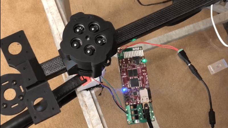
Cycloidal drives are fascinating pieces of hardware, and we’ve seen them showing up in part due to their suitability for 3D printing. The open source robot arm makers [Haddington Dynamics] are among those playing with a cycloidal drive concept, and tucked away in their August 2018 newsletter was a link they shared to a short but mesmerizing video of a prototype, which we’ve embedded below.
[Haddington Dynamics] are the folks responsible for the open source robot arm Dexter (which will be competing in the Hackaday Prize finals this year), and their interest in a cycloidal drive design sounds extremely forward-thinking. Their prototype consists of 3D printed parts plus some added hardware, but the real magic is in the manufacturing concept of the design. The idea is for the whole assembly to be 3D printed, stopping the printer at five different times to insert hardware. With a robot working in tandem with the printer, coordinating the print pauses with automated insertion of the appropriate hardware, the result will be a finished transmission unit right off the print bed. It’s a lofty goal, and really interesting advancement for small-scale fabrication.
We’ve seen similar drives recently in [Paul Gould]’s 3D Printed Robot Actuator which uses a cycloidal gearbox, as well as the incredibly smooth action of the cycloidal drive-inspired Abacus Drive.


Looking at the animated gif is there not loads of slop in the output shaft?
I think I am missing something here.
Nah, got it now. :)
Too early. :)
It’s a really confusing mechanism to figure out :)
Back when I made that gif I didn’t find any good illustrations and it took me some time to figure it out from 2D drawings. But I never ended up making a real, physical version – perhaps I could print one now.
Reminds one of Spirograph.
That was from you? Thanks for making that animation (and for putting it in the public domain!) It goes a very long way to helping understand how the thing works!
Hi ,
Last month i made a cycloid speed reducer soft for generate Rhino 3D script , it can help to made them yourself ;)
Take a look here : https://grabcad.com/library/cycloid-reducer-generator-for-rhino-3d-v2-0-1
Cheers.
According to Wikipedia “Cycloidal speed reducers are capable of relatively high ratios in compact sizes”. Other than that, this seems unnecessarily complicated and extremely subject to wear. Am I missing something?
Exactly what I was wondering. No mention of WHY they’re using this complicated gear type. Perhaps Haddington Dynamics hasn’t explained why, so the author of this article doesn’t know either?
“Because the individual parts are well-suited to 3D printing, this opens the door to easily prototyping custom designs and gearing ratios.” And much simpler toothed gears AREN’T well-suited to 3D printing?
Most gearing mechanism rely on much finer toothed gears; small, strong, and smooth surfaces, of the kind youd want for a reasonably competitive ‘normal’ gear, is indeed a combination you wont get with any contemporary 3d print technology.
I would assume it’s down to tooth size and cracks not propagating so easily from circular shapes as the sharper angled gear tooth.
I would say you can’t goo too wrong designing 3D printed stuff as if it was to be made from cheese rather than hardened steel.
Cyclodal reducers are used in industrial robots because they can handle high torques with very low backlash. A spur gear drivetrain (either helical or straight cut) is either higher backlash or higher wear depending on how it’s adjusted.
The low backlash features comes from the fact that the lobes are always in contact with most of the pins in the mechanism. This distributes the force pretty evenly too, hence the high torque capability.
Source: 10 years working for an industrial robot manufacturer.
Maybe a dumb question, but can a cycloidal drive be back-driven – e.g.: if I twist the output shaft hard enough, will it still spin the internal parts?
No
Depends. Most gear trains can be designed to be backdriveable.
It’s mosty a matter of friction, because the gear reduction ratio also amplifies any sliding friction. For example, a worm gear “cannot” be driven backwards, but if the thread angle is steep enough, it will slide back and rotate the input shaft just fine. That means the worm gear must be designed with a small enough gear ratio.
Also, vibration can make the “non-backdriveable” geartrains run backwards by preventing the gears from sticking (static friction vs. sliding friction) which greatly reduces the amount of torque needed.
Would that mean you have lower motor requirements for holding position and wouldn’t need to keep the coils energized to stay in place?
High-torque/low backlash – This looks like a natural to create a 3D printed telescope drive.
I was thinking more robotics. It’s been interesting in following that James Bruton fellow on YouTube building the OpenDog project. He’s used brushless CD motors and ball screws. It makes me wonder if a brushless DC motor hooked up to a cycloidal drive, which then drives a chain could be used to actuate lower limbs while still not requiring power to stay standing up.
A tiny CD motor? Like in a compact disc player? That seems too small. Do you mean something else?
What does this do that a simple windshield wiper mechanism doesn’t?
Flat stock drilled out with pressed bushings seem more simple to my mind, with the added benefit of not needing a control board since the motor is continually rotating. Is this arm designed for some sort of pick and place that requires multiple stop positions?
See below for an answer to your question.
Hi, I responded to a bunch of questions, including yours, in one post below.
I am having trouble understanding what the bearing is doing seperating the yellow and green parts of the animation.
The yellow bit is rotating at about 1/10 of the revs of the green bit so the bearing is essential. It really needs a GIF from above,as well it would be a lot easier to understand I think
The green and yellow parts are moving in opposite directions; so there has to be a bearing..
Thanks, it makes a lot more sense after my morning coffee.
D’oh, missed that. :)
For some 3D printed versions and some background, have a look here:
https://www.thingiverse.com/thing:79231
and here:
https://www.thingiverse.com/thing:81879
Hi I’m the engineer from Haddington Dynamics that designed this cycloidal drive and I’d like to answer a few of your questions:
Q: According to Wikipedia “Cycloidal speed reducers are capable of relatively high ratios in compact sizes”. Other than that, this seems unnecessarily complicated and extremely subject to wear. Am I missing something? – DoctorWizard
A: You are correct in that this is a fairly complicated mechanism and according the provided gif it would be subject to wear. We get around the wear by putting bearings on otherwise sliding surfaces. Complexity is essentially free when it comes to 3D printing so it’s not so much of a problem especially since the other options are also complex.
Our robot needs a gear ratio of somewhere between 50:1 and 100:1 to operate. The simplest solution would be a small gear of atleast 1 cm and large gear at somehwere between 0.5-1 meters! You can imagine what that would look like on a robot that’s less than a meter tall. So a compact and complex mechanism is needed here. This includes: planatary gears, strain wave gears, and cycloidal drives. Planetary gears are great at producing high gear ratios in small volumes but have an unacceptable amount of backlash. We’ve had mild success with strain wave gears (check out this video if you aren’t familar: https://www.youtube.com/watch?v=tMh-Axar3o8) as they can produce higher gear ratios at smaller volumes than planetary gears and are known for having no backlash. However we were measuring what we call ‘smooth backlash’ where there isn’t a sudden jump but instead the mechanism deforms when the load changes direction.
There is also the problem of having very small teeth which become the limiting factor for max load. These strain wave drives are fairly expensive, > $100 US each, and there is currently a shortage putting us on backorder for a number of months. These problems were the inspiration to try to make a cycloidal drive. Cycloidal drives have virtually no backlash, have large lobes that are always in contact, and have decently high gear ratios in small volumes.
The cycloidal drive shown in the above pictures acheives a 55:1 gear ratio that fits in the same footprint as our 52:1 strain wave drives. The coolest part is it’s all 3D printed minus the bearings, nuts, and bolts. The real innovation is that we’re using a Markforged to print contunous carbon in the high load parts which hopefully mitigate flexibility and wear, and improve max load.
Q: Maybe a dumb question, but can a cycloidal drive be back-driven – e.g.: if I twist the output shaft hard enough, will it still spin the internal parts? – Joel B
A: It depends on the gear ratio and how much friction is in the system but yes cycloidals can be back drivable. Our 55:1 drive takes a decent amount of torque to be back driven so I’d say 55:1 is probably close to the maximum ratio you’d want to go to.
Q: What does this do that a simple windshield wiper mechanism doesn’t?
Flat stock drilled out with pressed bushings seem more simple to my mind, with the added benefit of not needing a control board since the motor is continually rotating. Is this arm designed for some sort of pick and place that requires multiple stop positions? -Leithoa
A: You are correct if there are only a few positions you need to go to a linkage with a simple continuous motor would be the way to go. In fact in my college days I designed 4 bar double dwelling linkage that would not only hit two positions but also pause on each of them for small amount of time. Let me tell you this thing took an entire semester to design and changing the positions would’ve been impossible. Robot’s are programmable so you could just type in a list of XYZ’s and time you’d want to stay in each position and it will do it. Or if that’s too much our particular Robot, Dexter, has ability to be trained: You just drag it through a motion and it will play it back. And that’s just one function. Our robot is 5-axis it can also rotate at each position and also do that throughout smooth continuous paths. It has power and IO on at it’s end and base so it can control tools and sensor synced up with it’s motions. Each joint can measure torque so it can be used as a haptic controller or measure forces and weights. Here are some additional videos if you’re interested:
https://www.youtube.com/watch?v=t5glGbEb8d4
https://www.facebook.com/ZSparkyThoughts/videos/214948589158880/
https://www.youtube.com/watch?v=B2Us1Gc3_Zc
Feel free to ask any more question :D
Thanks for sharing that added information, especially about the specific needs and details like bearings on the contact surfaces. That was a great read!
Is the output motion linear? Or are there little sinusoidal errors on the output for each turn off the input?
If so how big are the errors?
I saw the news coverage stating 5 micron. Wow! Is that one using this 3d printed gear? (It looked metallic inside)
How is the user able to back drive /train if this gear has friction and 55:1 ratio?
Sorry… I’m just seeing this now. Not sure why I didn’t get a notification.
The output is /mostly/ linear. The errors are /not/ caused by the turns, but by little irregularities in the print. And the errors are tiny. We haven’t measured them, but they are impossible to detect with the human eye.
The precision Dexter achieves is because of the encoders, not the drives. We run the drive forward or back constantly to get the encoder to show the exact position. The encoders are on each joint, so they show the actual position of the joint, not the position of the drive system.
You can back drive it because it’s really, really smooth. And because it’s not perfectly smooth, it does sort of stick and slip as you do so. The wave drives are so smooth that you
The coolest thing about this design is that it was done from a mathematical equation entered into the Dexter Development Environment to make the code for the CAD output. Turning math into reality!